
 Panasonic Ram Dash Linear Men's Shaver 6 Blades Craft Black ES-CLS9AX-KRam DASH and LINEAR shavings for fast shavings, deepest shavings, and skin that is easy on the skin Please be sure to take a look at the product's more than a minute's reading and what to look out for before you make a product! To request a return or exchange, please note that it is mandatory to provide a video of the unpacking of the package.
 TonePros GKS60K B Tuner Black Black"TonePros GKS60K B Tuner Black, Machine Heads for Electric Guitar, Locking machine heads, Sealed construction, Configuration: 6-in-line, bass side (left), Gear ratio: 18:1, Shaft diameter: 6 mm, Mounting diameter: 10 mm, ""Kidney"" style buttons, Colour: Black"
 TonePros GKL60K-B Locking Tuner BL Black"TonePros GKL60K-B Locking Tuner BL, Machine Heads for Electric Guitar, Locking machine heads, Sealed design, Configuration: 6-in-line, bass side (left), Gear ratio: 18:1, Shaft diameter: 6 mm, Installation diameter: 10 mm, ""Small Kidney"" style buttons, Colour: Black"
 Moover : Moteur pour abri de piscine jusqu'a abri - CMoover : Le moteur pour abri piscine ! Vous avez investi dans un abri de piscine mais quand il s’agit de profiter de votre piscine, il vous faut l’ouvrir et le refermer une fois la baignade terminée. Si vous êtes à la recherche d’une solution pour motoriser votre abri de piscine, alors vous êtes au bon endroit. Grâce à la conception unique, vous pouvez installer le MOOVER sur des abris neufs ou existants de la société ALBIXON ainsi que d’autres marques. Il n'est pas possible d'installer le Moover sur : les abri sans rails, Avec angle négatifou plus lourd que 750 kilos - Moteur pour abri de piscine MOOVER - ALBIXON Un design élégant et une autonomie remarquabl Le design du Moover est pensé pour s’intégrer facilement dans vos extérieurs. Il est discret et prend très peu de place afin de préserver l’espace autour du bassin. De plus, Moover est doté de panneaux solaires qui lui permettent de fonctionner durant toute la saison estivale soit 3 mois. Grâce à sa batterie haute capacité dernière technologie, il peut fonctionner 1,5 heures en continu et jusqu’à 800 heures en mode veille. Une révolution dans l’utilisation de votre abri de piscine Développé en collaboration avec des ingénieurs de l’automobile, Moover vous permet de faire bouger votre abri de piscine sans effort . Son secret réside dans sa roue motorisée située à l’intérieur du boîtier. Il vous suffit d’appuyer sur un bouton pour ensuite piquer une tête, Moover vous fait gagner du temps et économiser vos efforts. Et quand vous ne souhaitez pas activer l'assistance de Moover, il vous suffit de dévisser l’écrou papillon afin de relâcher la pression de la roue. Grâce à la télécommande avec une portée de 30 mètres, vous pouvez facilement contrôler l’ouverture et la fermeture de votre abri de piscine. Et elle est si simple d’utilisation que tous les membres de la famille peuvent l’utiliser. Motoriser votre abri de piscine devient un jeu d’enfant : Moover est livré avec une notice de montage très bien détaillée qui vous permet de monter facilement le système d’ouverture et de fermeture de l’abri de piscine. Vous pouvez le faire seul, cela ne vous prendra que quelques heures. Et n’oubliez pas que les experts de Distripool sont à votre disposition pour vous aider à installer votre Moover. Moover s'adapte sur tous les abris de piscine dont le pas des arcs est de 1063 mm et le plan latéral ne présente pas d'angle d'incidence négatif. . Fiche technique : Moteur MOOVER pour abri de piscine Photo du MOOVER ALBIXON
- Moover : Moteur pour abri de piscine jusqu'a abri - CMoover : Le moteur pour abri piscine ! Vous avez investi dans un abri de piscine mais quand il s’agit de profiter de votre piscine, il vous faut l’ouvrir et le refermer une fois la baignade terminée. Si vous êtes à la recherche d’une solution pour motoriser votre abri de piscine, alors vous êtes au
 Robot de piscine Bestway Ruby Tri-moteursRobot piscine Bestway Ruby Tri-moteurs - Technologie sans fil Nettoyage optimisé du fond et des parois jusqu’à la ligne d’eau Ruby est un petit joyau dans l’univers des robots électriques pour piscines : il allie les avantages de la technologie sans fil à l’aisance de déplacement des robots électriques équipés de 3 moteurs. Fini les càbles emmêlés ou trop courts pour aller nettoyer correctement les angles de la piscine, le robot Bestway Ruby a toute la liberté nécessaire pour se déplacer partout à l’intérieur de votre piscine et il a la puissance nécessaire pour remonter les parois pour y aspirer les saletés qui s’y déposent. La puissance de ses 3 moteurs lui permet de se déplacer et monter aux parois sans affaiblir la puissance d’aspiration et donc conserver une qualité de filtration constante au cours de son cycle de nettoyage de 90 minutes. La batterie qui équipe le robot Ruby lui permet d’avoir la puissance nécessaire pour effectuer un nettoyage d’entretien complet en 90 minutes, elle pourra être rechargée en 7 à 8 heures une fois le robot sec et connecté à une source d’alimentation. Son poids plume lui permet d’être mis à l’eau et ressorti très facilement sans effort conséquent pour que le nettoyage de la piscine ne soit plus une contrainte. Le capteur d’eau qu’il embarque lui permet de démarrer automatiquement lorsque vous le plongez dans l’eau et commencer ainsi son travail de nettoyage. Les cassettes filtrantes qui équipent ce modèle Ruby ont une capacité importante pour lui permettre d’aller au bout de son cycle de nettoyage sans arrêt prématuré pour motif de filtre plein, et elles ont une capacité de filtration de 180 microns qui est particulièrement adaptée aux piscines où l’on retrouves des débris végétaux, morceaux de feuilles, terre, etc... Ruby détectera automatiquement sa sortie de l’eau gràce à ce même capteur et se coupera donc pour préserver totalement son moteur. Qualité de conception et de fabrication Bestway Gràce à son savoir-faire, Bestway propose aujourd’hui le modèle Ruby, un robot autonome qui vous libère des contraintes des càbles et permet un nettoyage efficace du fond à la ligne d’eau, adapté à tout type de piscine. La batterie Lithium-ion permet de conserver des performances constantes tout au long du cycle de nettoyage. C’est un élément technique important trop souvent négligé et qui sera pourtant déterminant pour une durée de vie optimale. Ruby n’est retenu par aucun càble, cela lui permet d’avoir une amplitude maximale pour ses déplacements. Plus petit et plus léger qu’un robot électrique classique, il sera plus facile à manipuler et vous facilitera grandement l’entretien de votre piscine. Pour quelles piscines ? Tout type de piscines hors-sol ou enterrées jusqu’à 8 x 4m Tout type de formes Fond plat et pentes composées jusqu’à 30° Tout revêtement (liner, carrelage, béton peint, coque, etc...) Informations complémentaires Batterie rechargeable : Lithium-ion 8800 mAh Autonomie de la batterie : 1h30 (soit 90...
 Moover : Moteur pour abri de piscine jusqu'a abri - AMoover : Le moteur pour abri piscine ! Vous avez investi dans un abri de piscine mais quand il s’agit de profiter de votre piscine, il vous faut l’ouvrir et le refermer une fois la baignade terminée. Si vous êtes à la recherche d’une solution pour motoriser votre abri de piscine, alors vous êtes au bon endroit. Grâce à la conception unique, vous pouvez installer le MOOVER sur des abris neufs ou existants de la société ALBIXON ainsi que d’autres marques. Il n'est pas possible d'installer le Moover sur : les abri sans rails, Avec angle négatifou plus lourd que 750 kilos - Moteur pour abri de piscine MOOVER - ALBIXON Un design élégant et une autonomie remarquabl Le design du Moover est pensé pour s’intégrer facilement dans vos extérieurs. Il est discret et prend très peu de place afin de préserver l’espace autour du bassin. De plus, Moover est doté de panneaux solaires qui lui permettent de fonctionner durant toute la saison estivale soit 3 mois. Grâce à sa batterie haute capacité dernière technologie, il peut fonctionner 1,5 heures en continu et jusqu’à 800 heures en mode veille. Une révolution dans l’utilisation de votre abri de piscine Développé en collaboration avec des ingénieurs de l’automobile, Moover vous permet de faire bouger votre abri de piscine sans effort . Son secret réside dans sa roue motorisée située à l’intérieur du boîtier. Il vous suffit d’appuyer sur un bouton pour ensuite piquer une tête, Moover vous fait gagner du temps et économiser vos efforts. Et quand vous ne souhaitez pas activer l'assistance de Moover, il vous suffit de dévisser l’écrou papillon afin de relâcher la pression de la roue. Grâce à la télécommande avec une portée de 30 mètres, vous pouvez facilement contrôler l’ouverture et la fermeture de votre abri de piscine. Et elle est si simple d’utilisation que tous les membres de la famille peuvent l’utiliser. Motoriser votre abri de piscine devient un jeu d’enfant : Moover est livré avec une notice de montage très bien détaillée qui vous permet de monter facilement le système d’ouverture et de fermeture de l’abri de piscine. Vous pouvez le faire seul, cela ne vous prendra que quelques heures. Et n’oubliez pas que les experts de Distripool sont à votre disposition pour vous aider à installer votre Moover. Moover s'adapte sur tous les abris de piscine dont le pas des arcs est de 1063 mm et le plan latéral ne présente pas d'angle d'incidence négatif. . Fiche technique : Moteur MOOVER pour abri de piscine Photo du MOOVER ALBIXON
- Moover : Moteur pour abri de piscine jusqu'a abri - BMoover : Le moteur pour abri piscine ! Vous avez investi dans un abri de piscine mais quand il s’agit de profiter de votre piscine, il vous faut l’ouvrir et le refermer une fois la baignade terminée. Si vous êtes à la recherche d’une solution pour motoriser votre abri de piscine, alors vous êtes au bon endroit. Grâce à la conception unique, vous pouvez installer le MOOVER sur des abris neufs ou existants de la société ALBIXON ainsi que d’autres marques. Il n'est pas possible d'installer le Moover sur : les abri sans rails, Avec angle négatifou plus lourd que 750 kilos - Moteur pour abri de piscine MOOVER - ALBIXON Un design élégant et une autonomie remarquabl Le design du Moover est pensé pour s’intégrer facilement dans vos extérieurs. Il est discret et prend très peu de place afin de préserver l’espace autour du bassin. De plus, Moover est doté de panneaux solaires qui lui permettent de fonctionner durant toute la saison estivale soit 3 mois. Grâce à sa batterie haute capacité dernière technologie, il peut fonctionner 1,5 heures en continu et jusqu’à 800 heures en mode veille. Une révolution dans l’utilisation de votre abri de piscine Développé en collaboration avec des ingénieurs de l’automobile, Moover vous permet de faire bouger votre abri de piscine sans effort . Son secret réside dans sa roue motorisée située à l’intérieur du boîtier. Il vous suffit d’appuyer sur un bouton pour ensuite piquer une tête, Moover vous fait gagner du temps et économiser vos efforts. Et quand vous ne souhaitez pas activer l'assistance de Moover, il vous suffit de dévisser l’écrou papillon afin de relâcher la pression de la roue. Grâce à la télécommande avec une portée de 30 mètres, vous pouvez facilement contrôler l’ouverture et la fermeture de votre abri de piscine. Et elle est si simple d’utilisation que tous les membres de la famille peuvent l’utiliser. Motoriser votre abri de piscine devient un jeu d’enfant : Moover est livré avec une notice de montage très bien détaillée qui vous permet de monter facilement le système d’ouverture et de fermeture de l’abri de piscine. Vous pouvez le faire seul, cela ne vous prendra que quelques heures. Et n’oubliez pas que les experts de Distripool sont à votre disposition pour vous aider à installer votre Moover. Moover s'adapte sur tous les abris de piscine dont le pas des arcs est de 1063 mm et le plan latéral ne présente pas d'angle d'incidence négatif. . Fiche technique : Moteur MOOVER pour abri de piscine Photo du MOOVER ALBIXON
- Moover : Moteur pour abri de piscine jusqu'a abri - AMoover : Le moteur pour abri piscine ! Vous avez investi dans un abri de piscine mais quand il s’agit de profiter de votre piscine, il vous faut l’ouvrir et le refermer une fois la baignade terminée. Si vous êtes à la recherche d’une solution pour motoriser votre abri de piscine, alors vous êtes au
- Moover : Moteur pour abri de piscine jusqu'a abri - BMoover : Le moteur pour abri piscine ! Vous avez investi dans un abri de piscine mais quand il s’agit de profiter de votre piscine, il vous faut l’ouvrir et le refermer une fois la baignade terminée. Si vous êtes à la recherche d’une solution pour motoriser votre abri de piscine, alors vous êtes au
 Volet immergé piscine moteur dans l'axe Roussillon IILe volet immergé piscine ROUSSILLON moteur dans l'axe est la solution idéale pour couvrir et sécurisé sa piscine. Le moteur est situé dans l'axe. C'est le modèle idéal quand la piscine est déjà en eau. Ce volet immergé est fabriqué en France, il est aussi conforme à la norme NF P90-308. Prix à partir de : piscine de 5.00 x 3.00 m Sans escalier - Caillebotis ALU - Sans cloison de séparation (hors transport) - Volet immergé piscine ECA ROUSSILLON Moteur dans l'axe Enrouleur complet avec moteur dans l'axe. Axe + moteur et coffret garantie 4 ans + coffret avec contact pour électrolyseur au sel . Commutateur à clé déportée 3 positions avec contact maintenue . Dimensions maxi 8.03 x 12.00 m Avec Fin de course intégré Lames de couleur au même prix que les blanches !! Lames 71 mm - épaisseur 17 mm. PVC traité anti-tâche et anti UV Les lames sont fabriquées en PVC stabilisé au calcium de ZINC afin d'éviter les tâches. A chaque extrémité de la lame, des bouchons soudés assurent l'étanchéité du tablier. Des ailettes de 20 mm assurent la finition. Système de sécurité : Le nombre de système de sécurité est déterminé par la largueur du bassin. En fonction des cotes fournies sur la fiche de fabrication, ECA se réserve le droit de modifier le nombre de système de sécurité. Ces chiffres sont indiqués sous réserve et seront considérablement plus élevés dans des climats plus chauds et en cas de vent. < à 3 m = 2 par largueur de 3 à 5 m = 3 par largueur de 5 à 7 m = 4 par largueur En option : système de sécurité sur arase. Caillebotis conforme à la norme NF P-90-308 : Le caillebotis repose d'une part sur la poutrelle et d'autre part sur le mesure de l'arase. Nos caillebotis sont composés de lame de 125 mm. Nous vous rappelons qu'il n'est pas possible de couper les lames pour en réduire la largueur ( prévoir découpe des margelles ). 3 types de caillebotis : En aluminium double face blanc. ( sable et gris en option ). En bois IPE ( en option ) En composite de couleur bois ou gris ( en option ) 2 tailles : 700 x 1000 mm. 900 x 1000 ( en option ) Sur mesure ( en option ) Poutrelle en aluminium au choix ! Poutrelle en alu de 100 x 70 mm 3 couleurs : boitier réglable, boitier à fixer sur la paroi Poutrelle en alu de 100 x 110 mm 3 couleurs : boitier réglable, boitier à fixer sur la paroi, boitier pour profil liner horizontal, boitier profil liner vertical Blanche, sable ou grise
- Volet immergé piscine moteur dans l'axe Roussillon IILe volet immergé piscine ROUSSILLON moteur dans l'axe est la solution idéale pour couvrir et sécurisé sa piscine. Le moteur est situé dans l'axe. C'est le modèle idéal quand la piscine est déjà en eau. Ce volet immergé est fabriqué en France, il est aussi conforme à la norme NF P90-308. Prix à part
- Robot de piscine Bestway Ruby Tri-moteursRobot piscine Bestway Ruby Tri-moteurs - Technologie sans fil Nettoyage optimisé du fond et des parois jusqu’à la ligne d’eau Ruby est un petit joyau dans l’univers des robots électriques pour piscines : il allie les avantages de la technologie sans fil à l’aisance de déplacement des robots électriques équipés de 3 moteurs. Fini les càbles emmêlés ou trop courts pour aller nettoyer correctement les angles de la piscine, le robot Bestway Ruby a toute la liberté nécessaire pour se déplacer partout à l’intérieur de votre piscine et il a la puissance nécessaire pour remonter les parois pour y aspirer les saletés qui s’y déposent. La puissance de ses 3 moteurs lui permet de se déplacer et monter aux parois sans affaiblir la puissance d’aspiration et donc conserver une qualité de filtration constante au cours de son cycle de nettoyage de 90 minutes. La batterie qui équipe le robot Ruby lui permet d’avoir la puissance nécessaire pour effectuer un nettoyage d’entretien complet en 90 minutes, elle pourra être rechargée en 7 à 8 heures une fois le robot sec et connecté à une source d’alimentation. Son poids plume lui permet d’être mis à l’eau et ressorti très facilement sans effort conséquent pour que le nettoyage de la piscine ne soit plus une contrainte. Le capteur d’eau qu’il embarque lui permet de démarrer automatiquement lorsque vous le plongez dans l’eau et commencer ainsi son travail de nettoyage. Les cassettes filtrantes qui équipent ce modèle Ruby ont une capacité importante pour lui permettre d’aller au bout de son cycle de nettoyage sans arrêt prématuré pour motif de filtre plein, et elles ont une capacité de filtration de 180 microns qui est particulièrement adaptée aux piscines où l’on retrouves des débris végétaux, morceaux de feuilles, terre, etc... Ruby détectera automatiquement sa sortie de l’eau gràce à ce même capteur et se coupera donc pour préserver totalement son moteur. Qualité de conception et de fabrication Bestway Gràce à son savoir-faire, Bestway propose aujourd’hui le modèle Ruby, un robot autonome qui vous libère des contraintes des càbles et permet un nettoyage efficace du fond à la ligne d’eau, adapté à tout type de piscine. La batterie Lithium-ion permet de conserver des performances constantes tout au long du cycle de nettoyage. C’est un élément technique important trop souvent négligé et qui sera pourtant déterminant pour une durée de vie optimale. Ruby n’est retenu par aucun càble, cela lui permet d’avoir une amplitude maximale pour ses déplacements. Plus petit et plus léger qu’un robot électrique classique, il sera plus facile à manipuler et vous facilitera grandement l’entretien de votre piscine. Pour quelles piscines ? Tout type de piscines hors-sol ou enterrées jusqu’à 8 x 4m Tout type de formes Fond plat et pentes composées jusqu’à 30° Tout revêtement (liner, carrelage, béton peint, coque, etc...) Informations complémentaires Batterie rechargeable : Lithium-ion 8800 mAh Autonomie de la batterie : 1h30 (soit 90...
 Aucun VEVOR-Moteur de pompe de piscine, cadre 56Y, 1/1 V, 115V, 230 tr/min, 60Hz, 3450 tr/min, casse-tête,VEVOR-Moteur de pompe de piscine, cadre 56Y, 1/1 V, 115V, 230 tr/min, 60Hz, 3450 tr/min, casse-tête,
 VEVOR 110 V/230 V pompe de piscine 1.5HP/1HP moteur entrée/hors terre entrée/sortie 41/47.6/ piedsVEVOR 110 V/230 V pompe de piscine 1.5HP/1HP moteur entrée/hors terre entrée/sortie 41/47.6/ pieds
 Aucun Pompe à moteur sans balais à énergie solaire, moteur de compteur de piscine, contrôle de chargePompe à moteur sans balais à énergie solaire, moteur de compteur de piscine, contrôle de charge
 homgeek Robot nettoyeur de piscine sans fil 30W, étanche, moteurs à double entraînement, aspirateur deRobot nettoyeur de piscine sans fil 30W, étanche, moteurs à double entraînement, aspirateur de
 Other Genkinno erian SE-Aspirateur de piscine robotique sans fil, moteur sans balais Max 100W, navigationGenkinno erian SE-Aspirateur de piscine robotique sans fil, moteur sans balais Max 100W, navigation
 Robot piscine Zodiac CNX 20Le robot aspirateur de piscine Zodiac CNX 20 est prévu pour le nettoyage des piscines jusqu'à 10x5 m. 2 programmes : Fond seul (1h30) / Fond, parois, ligne d'eau (2h30) Aspiration Vortex cyclonique : 30%+ puissante Compatible toutes formes, tous fonds, tous revêtements Double moteur de traction pour une motricité maximale Accès facile au filtre par le dessus du robot Capot transparent : visibilité de l'encrassement du filtre Ultra léger (8 kg)
 Robot piscine Zodiac OT 3200 Tornax - TILERobot piscine Zodiac OT 3200 Le robot de piscine électrique Zodiac Vortex OT 3200, il permet de nettoyer le fond et les parois pour votre piscine jusqu'à 9 x 4 m. Il permet grâce à ses brosses actives de décoller les débris pour être aspirés grâce à un puissant moteur. Toute la technologie ZODIAC à petit prix Mais le gros point fort de ce robot électrique OT3200, c'est son poids ! Seulement 5.5 kg. Le robot fond et paroi le plus léger du marché. Version TILD : Compatible tout revêtement : Liner, béton carrelage et coque polyester. - Robot piscine Tornax OT 3200 TILE by Zodiac Voici la nouvelle collection de robot fond + paroi de chez ZODIAC. Le robot Vortex OV3400 by zodiac. Zodiac a travaillé un nouveau look design et moderne tout en travaillant sur le poids grâce à des matériaux le plus léger possible. Robot Zodiac OT 3200 : Fiche technique
 Pompe piscine STA RITE PENTAIR de 16 m3/h (1CV ) - TriphaséPompe piscine STA - RITE modèle P-STR La pompe piscine STA - RITE est la pompe la plus haut de gamme, résistante à toutes épreuves, des rendement surpuissant, un moteur ultra silencieux. Le moteur bénéfice de la technologie PENTAIR éprouvé et efficace renforcé en fibre de verre, une turbine haute pression pour un débit maximale COMPATIBLE ELECTROLYSEUR - Pompe STA RITE 5P2R de 3/4 à 1.5 CV en mono La pompe STA - RITE de la série 5P2R est en matériau de synthèse renforcé à la fibre de verre et obtenue par moulage de haute précision. Moteur Moteur européen conforme aux normes “CE” et muni d’une protection IP 55. La conception spéciale du diffuseur assure un auto-amorçage très efficace. Embase La pompe STA RITE 5P2R est montée sur une embase surélevée, stable, rigide et antivibrations. La hauteur de l’embase préserve le moteur de l’humidité et des souillures. Collier d’assemblage Le collier d’assemblage, en acier inoxydable, permet un démontage rapide de l’ensemble et un accès aisé aux pièces mobiles. Obtenue par le moulage sous pression, la turbine est conçue pour délivrer une hauteur manométrique élevée. Sa finition et son équilibrage dynamique lui assurent un fonctionnement silencieux et un excellent rendement. Le couvercle transparent du préfiltre permet facilement de vérifier l’état de colmatage du panier. Le couvercle a un ø de 127 mm et résiste à une pression de 4 bar. le panier du préfiltre est verrouillable et protège la turbine des impuretés. Construction Le matériau utilisé pour la fabrication de la pompe sta rite et du préfiltre autorise une pression de service élevée. Testé pendant plusieurs années ce matériau a des caractéristiques incomparables et résiste même à des variations de températures importantes. Presse-étoupe Comme sur des millions de pompes STA-RITE une étanchéité parfaite est obtenue par le presse-étoupe en céramique de carbone finement polie et surfacée. Données Techniques La pompes de la série 5P2R est une pompe centrifuge qui est principalement conçue pour l’application dans la piscine, en combinaison avec un filtre de piscine.
- Pompe piscine STA RITE PENTAIR de 18 m3/h (1.5CV ) - TriphaséPompe piscine STA - RITE modèle P-STR La pompe piscine STA - RITE est la pompe la plus haut de gamme, résistante à toutes épreuves, des rendement surpuissant, un moteur ultra silencieux. Le moteur bénéfice de la technologie PENTAIR éprouvé et efficace renforcé en fibre de verre, une turbine haute pression pour un débit maximale COMPATIBLE ELECTROLYSEUR - Pompe STA RITE 5P2R de 3/4 à 1.5 CV en mono La pompe STA - RITE de la série 5P2R est en matériau de synthèse renforcé à la fibre de verre et obtenue par moulage de haute précision. Moteur Moteur européen conforme aux normes “CE” et muni d’une protection IP 55. La conception spéciale du diffuseur assure un auto-amorçage très efficace. Embase La pompe STA RITE 5P2R est montée sur une embase surélevée, stable, rigide et antivibrations. La hauteur de l’embase préserve le moteur de l’humidité et des souillures. Collier d’assemblage Le collier d’assemblage, en acier inoxydable, permet un démontage rapide de l’ensemble et un accès aisé aux pièces mobiles. Obtenue par le moulage sous pression, la turbine est conçue pour délivrer une hauteur manométrique élevée. Sa finition et son équilibrage dynamique lui assurent un fonctionnement silencieux et un excellent rendement. Le couvercle transparent du préfiltre permet facilement de vérifier l’état de colmatage du panier. Le couvercle a un ø de 127 mm et résiste à une pression de 4 bar. le panier du préfiltre est verrouillable et protège la turbine des impuretés. Construction Le matériau utilisé pour la fabrication de la pompe sta rite et du préfiltre autorise une pression de service élevée. Testé pendant plusieurs années ce matériau a des caractéristiques incomparables et résiste même à des variations de températures importantes. Presse-étoupe Comme sur des millions de pompes STA-RITE une étanchéité parfaite est obtenue par le presse-étoupe en céramique de carbone finement polie et surfacée. Données Techniques La pompes de la série 5P2R est une pompe centrifuge qui est principalement conçue pour l’application dans la piscine, en combinaison avec un filtre de piscine.
 Pompe piscine STA RITE PENTAIR de 12 m3/h en mono ( 3/4 CV )Pompe piscine STA - RITE modèle P-STR La pompe piscine STA - RITE est la pompe la plus haut de gamme, résistante à toutes épreuves, des rendement surpuissant, un moteur ultra silencieux. Le moteur bénéfice de la technologie PENTAIR éprouvé et efficace renforcé en fibre de verre, une turbine haute pression pour un débit maximale COMPATIBLE ELECTROLYSEUR - Pompe STA RITE 5P2R de 3/4 à 1.5 CV en mono La pompe STA - RITE de la série 5P2R est en matériau de synthèse renforcé à la fibre de verre et obtenue par moulage de haute précision. Moteur Moteur européen conforme aux normes “CE” et muni d’une protection IP 55. La conception spéciale du diffuseur assure un auto-amorçage très efficace. Embase La pompe STA RITE 5P2R est montée sur une embase surélevée, stable, rigide et antivibrations. La hauteur de l’embase préserve le moteur de l’humidité et des souillures. Collier d’assemblage Le collier d’assemblage, en acier inoxydable, permet un démontage rapide de l’ensemble et un accès aisé aux pièces mobiles. Obtenue par le moulage sous pression, la turbine est conçue pour délivrer une hauteur manométrique élevée. Sa finition et son équilibrage dynamique lui assurent un fonctionnement silencieux et un excellent rendement. Le couvercle transparent du préfiltre permet facilement de vérifier l’état de colmatage du panier. Le couvercle a un ø de 127 mm et résiste à une pression de 4 bar. le panier du préfiltre est verrouillable et protège la turbine des impuretés. Construction Le matériau utilisé pour la fabrication de la pompe sta rite et du préfiltre autorise une pression de service élevée. Testé pendant plusieurs années ce matériau a des caractéristiques incomparables et résiste même à des variations de températures importantes. Presse-étoupe Comme sur des millions de pompes STA-RITE une étanchéité parfaite est obtenue par le presse-étoupe en céramique de carbone finement polie et surfacée. Données Techniques La pompes de la série 5P2R est une pompe centrifuge qui est principalement conçue pour l’application dans la piscine, en combinaison avec un filtre de piscine.
- Robot piscine Zodiac CNX 25Le robot aspirateur de piscine Zodiac CNX 25 est prévu pour le nettoyage des piscines jusqu'à 10x5 m. 2 programmes : Fond seul (1h30) et Fond, parois, ligne d'eau (2h30) Aspiration Vortex cyclonique : 30%+ puissante Compatible toutes formes, tous fonds, tous revêtements Double moteur de traction pour une motricité maximale Accès facile au filtre par le dessus du robot Capot transparent : visibilité de l'encrassement du filtre Double filtration : finesse de filtration 150/60 µ via deux bacs filtratns Ultra léger (8 kg)
- Pompe piscine STA RITE PENTAIR de 12 m3/h ( 3/4 CV ) - TriphaséPompe piscine STA - RITE modèle P-STR La pompe piscine STA - RITE est la pompe la plus haut de gamme, résistante à toutes épreuves, des rendement surpuissant, un moteur ultra silencieux. Le moteur bénéfice de la technologie PENTAIR éprouvé et efficace renforcé en fibre de verre, une turbine haute pression pour un débit maximale COMPATIBLE ELECTROLYSEUR - Pompe STA RITE 5P2R de 3/4 à 1.5 CV en mono La pompe STA - RITE de la série 5P2R est en matériau de synthèse renforcé à la fibre de verre et obtenue par moulage de haute précision. Moteur Moteur européen conforme aux normes “CE” et muni d’une protection IP 55. La conception spéciale du diffuseur assure un auto-amorçage très efficace. Embase La pompe STA RITE 5P2R est montée sur une embase surélevée, stable, rigide et antivibrations. La hauteur de l’embase préserve le moteur de l’humidité et des souillures. Collier d’assemblage Le collier d’assemblage, en acier inoxydable, permet un démontage rapide de l’ensemble et un accès aisé aux pièces mobiles. Obtenue par le moulage sous pression, la turbine est conçue pour délivrer une hauteur manométrique élevée. Sa finition et son équilibrage dynamique lui assurent un fonctionnement silencieux et un excellent rendement. Le couvercle transparent du préfiltre permet facilement de vérifier l’état de colmatage du panier. Le couvercle a un ø de 127 mm et résiste à une pression de 4 bar. le panier du préfiltre est verrouillable et protège la turbine des impuretés. Construction Le matériau utilisé pour la fabrication de la pompe sta rite et du préfiltre autorise une pression de service élevée. Testé pendant plusieurs années ce matériau a des caractéristiques incomparables et résiste même à des variations de températures importantes. Presse-étoupe Comme sur des millions de pompes STA-RITE une étanchéité parfaite est obtenue par le presse-étoupe en céramique de carbone finement polie et surfacée. Données Techniques La pompes de la série 5P2R est une pompe centrifuge qui est principalement conçue pour l’application dans la piscine, en combinaison avec un filtre de piscine.
- Pompe piscine STA RITE PENTAIR de 8m3/h en mono ( 1/2 CV )Pompe piscine STA RITE modèle P-STR La pompe piscine STA RITE P-STR est la pompe la plus haut de gamme, résistante à toutes épreuves, des rendement surpuissant, un moteur ultra silencieux. Le moteur bénéfice de la technologie PENTAIR éprouvé et efficace renforcé en fibre de verre, une turbine haute pression pour un débit maximale COMPATIBLE ELECTROLYSEUR - Pompe piscine STA RITE modèle P-STR : Ancienne 5P2R La pompe STA - RITE de la série P-STR est en matériau de synthèse renforcé à la fibre de verre et obtenue par moulage de haute précision. Moteur Moteur européen conforme aux normes “CE” et muni d’une protection IP 55. La conception spéciale du diffuseur assure un auto-amorçage très efficace. Embase La pompe STA RITE P-STR est montée sur une embase surélevée, stable, rigide et antivibrations. La hauteur de l’embase préserve le moteur de l’humidité et des souillures. Collier d’assemblage Le collier d’assemblage, en acier inoxydable, permet un démontage rapide de l’ensemble et un accès aisé aux pièces mobiles. Obtenue par le moulage sous pression, la turbine est conçue pour délivrer une hauteur manométrique élevée. Sa finition et son équilibrage dynamique lui assurent un fonctionnement silencieux et un excellent rendement. Le couvercle transparent du préfiltre permet facilement de vérifier l’état de colmatage du panier. Le couvercle a un ø de 127 mm et résiste à une pression de 4 bar. le panier du préfiltre est verrouillable et protège la turbine des impuretés. Construction Le matériau utilisé pour la fabrication de la pompe sta rite et du préfiltre autorise une pression de service élevée. Testé pendant plusieurs années ce matériau a des caractéristiques incomparables et résiste même à des variations de températures importantes. Presse-étoupe Comme sur des millions de pompes STA-RITE une étanchéité parfaite est obtenue par le presse-étoupe en céramique de carbone finement polie et surfacée. Données Techniques La pompes de la série 5P2R est une pompe centrifuge qui est principalement conçue pour l’application dans la piscine, en combinaison avec un filtre de piscine. Fiche technique Pompe PENTAIR : STA RITE modèle P-STR : Ancienne 5P2R
- Robot piscine Zodiac OT 3200 Tornax - TILERobot piscine Zodiac OT 3200 Le robot de piscine électrique Zodiac Vortex OT 3200, il permet de nettoyer le fond et les parois pour votre piscine jusqu'à 9 x 4 m. Il permet grâce à ses brosses actives de décoller les débris pour être aspirés grâce à un puissant moteur. Toute la technologie ZODIAC à
News and research before you hear about it on CNBC and others. Claim your 1-week free trial to StreetInsider Premium here.
UNITED STATES
SECURITIES AND EXCHANGE COMMISSION
Washington, D.C. 20549
FORM 6-K
REPORT OF FOREIGN PRIVATE ISSUER PURSUANT TO RULE 13a-16 OR 15d-16
UNDER THE SECURITIES EXCHANGE ACT OF 1934
For the month of August 2020
Commission File Number: 001-33153
ENDEAVOUR SILVER CORP.
(Translation of registrant’s name into English)
#1130-609 Granville Street
Vancouver, British Columbia, Canada V7Y 1G5
(Address of principal executive offices)
Indicate by check mark whether the registrant files or will file annual reports under cover Form 20-F or Form 40-F.
[ ] Form 20-F [ x ] Form 40-F
Indicate by check mark if the registrant is submitting the Form 6-K in paper as permitted by Regulation S-T Rule 101(b)(1): [ ]
Indicate by check mark if the registrant is submitting the Form 6-K in paper as permitted by Regulation S-T Rule 101(b)(7): [ ]
Indicate by check mark whether by furnishing the information contained in this Form, the registrant is also thereby furnishing the information to the Commission pursuant to Rule 12g3-2(b) under the Securities Exchange Act of 1934.
Yes [ ] No [ x ]
If « Yes » is marked, indicate below the file number assigned to the registrant in connection with Rule 12g3-2(b): 82- _________
SUBMITTED HEREWITH
Exhibits
SIGNATURES
Pursuant to the requirements of the Securities Exchange Act of 1934, the registrant has duly caused this report to be signed on its behalf by the undersigned, thereunto duly authorized.
| Endeavour Silver Corp. | ||
| (Registrant) | ||
| Date: August 6, 2020 | By: | /s/ Bradford Cooke |
| Bradford Cooke | ||
| Title: | CEO | |
|
|
|
104698-02-RPT-001 |
Endeavour Silver Corp
|
NI 43-101 Technical Report |
July 31, 2020 |
Prepared for: Endeavour Silver Corp.
Prepared by: Ausenco Engineering Canada
Qualified Persons
Robin Kalanchey, P.Eng. – Ausenco Engineering Canada • Michael Petrina, P.Eng. – Moose Mountain Technical Services • Humberto F. Preciado, P.E. – Wood • Eugene Puritch, P.Eng., FEC, CET – P&E Mining Consultants Inc. • David Burga, P.Geo. – P&E Mining Consultants Inc. • Yungang Wu, P.Geo. – P&E Mining Consultants Inc. • Michael Levy, P.Eng. – JDS Energy & Mining Inc. • Eugenio Iasillo, P.E. – Process Engineering LLC
TABLE OF CONTENTS
| 1 Summary | 1-1 |
| 1.1 Overview | 1-1 |
| 1.2 Property Description and Location | 1-1 |
| 1.3 Accessibility, Climate, Local Resources, Infrastructure & Physiography | 1-2 |
| 1.4 History | 1-3 |
| 1.5 Geology and Mineralization | 1-5 |
| 1.6 Deposit Types | 1-5 |
| 1.7 Exploration | 1-5 |
| 1.8 Drilling | 1-6 |
| 1.9 Sample Preparation, Analyses and Security | 1-7 |
| 1.10 Data Verification | 1-7 |
| 1.11 Mineral Processing and Metallurgical Testing | 1-7 |
| 1.12 Mineral Resource Estimate | 1-10 |
| 1.13 Mineral Reserve Estimate | 1-11 |
| 1.14 Mining Methods | 1-12 |
| 1.15 Recovery Methods | 1-15 |
| 1.16 Project Infrastructure | 1-18 |
| 1.16.1 Access | 1-18 |
| 1.16.2 Power | 1-18 |
| 1.16.3 Tailings Storage Facility | 1-18 |
| 1.16.4 Accommodation | 1-19 |
| 1.16.5 Buildings | 1-19 |
| 1.16.6 Water Management | 1-19 |
| 1.17 Market Studies and Contracts | 1-19 |
| 1.18 Environmental Studies, Permitting, and Social or Community Impact | 1-20 |
| 1.19 Capital and Operating Costs | 1-20 |
| 1.19.1 Capital Cost | 1-20 |
| 1.19.2 Operating Cost | 1-21 |
| 1.20 Economic Analysis | 1-22 |
| 1.20.1 Financial Model Parameters | 1-22 |
| 1.20.2 Economic Analysis | 1-22 |
| 1.20.3 Sensitivity Analysis | 1-24 |
| 1.21 Conclusions and Recommendations | 1-27 |
| 1.21.1 Overall | 1-27 |
| 1.21.2 Exploration | 1-27 |
| 1.21.3 Mineral Resource Estimations | 1-27 |
| 1.21.4 Mineral Reserve and Mining Methods | 1-28 |
| 1.21.5 Metallurgical Testwork | 1-28 |
| 1.21.6 Recovery Methods | 1-29 |
| 1.21.7 Site Infrastructure | 1-29 |
| 1.21.8 Water Management | 1-29 |
| 1.21.9 Tailings Management Facility | 1-30 |
| 1.21.10 Environmental, Permitting & Community Relations | 1-30 |
| 2 Introduction | 2-1 |
| 2.1 Introduction | 2-1 |
104698-02-RX-RPT-001
Rev: A
Date: July 31, 2020
| 2.2 Terms of Reference | 2-1 |
| 2.3 Sources of Information | 2-1 |
| 2.4 Qualified Persons | 2-1 |
| 2.5 Site Visits and Scope of Personal Inspection | 2-2 |
| 2.6 Effective Dates | 2-2 |
| 2.7 Previous Technical Reports | 2-2 |
| 2.8 Units and Currency | 2-3 |
| 3 Reliance on Other Experts | 3-1 |
| 3.1 Legal Status | 3-1 |
| 3.2 Baseline Studies, Environmental, and Permitting | 3-1 |
| 4 Property Description and Location | 4-1 |
| 4.1 Location | 4-1 |
| 4.2 Mexican Regulations for Mineral Concessions | 4-2 |
| 4.3 Property Description and Tenure | 4-2 |
| 4.4 Surface Rights | 4-6 |
| 4.5 Water Rights | 4-7 |
| 4.6 Royalties and Encumbrances | 4-7 |
| 4.7 Permitting Considerations | 4-7 |
| 4.8 Environmental Considerations | 4-7 |
| 4.9 Social License Considerations | 4-7 |
| 4.10 QP Comments on « Item 4; Property Description and Location » | 4-7 |
| 5 Accessibility, Climate, Local Resources, Infrastructure and Physiography | 5-1 |
| 5.1 Accessibility | 5-1 |
| 5.2 Local Resources and Infrastructure | 5-1 |
| 5.3 Climate | 5-1 |
| 5.4 Physiography | 5-1 |
| 5.5 Infrastructure | 5-2 |
| 6 History | 6-1 |
| 6.1 San Sebastian Del Oeste Mining District | 6-1 |
| 6.2 Previous Mineral Resource and Mineral Reserve Estimates | 6-2 |
| 6.3 Past Production History | 6-4 |
| 7 Geological Setting and Mineralization | 7-1 |
| 7.1 Regional Geology | 7-1 |
| 7.2 Local Geology | 7-2 |
| 7.3 Deposit Geology | 7-3 |
| 7.4 Structure | 7-4 |
| 7.5 Alteration | 7-4 |
| 7.6 Mineralization | 7-4 |
| 8 Deposit Types | 8-1 |
| 8.1 Low-Sulphidation Epithermal Deposits | 8-1 |
| 8.1.1 Geological Setting | 8-1 |
| 8.1.2 Mineralization | 8-1 |
| 8.1.3 Alteration | 8-2 |
| 8.2 Applicability of the Low-Sulphidation Model to the Terronera Project | 8-2 |
| 8.3 QP Comments on « Item 8: Deposit Types » | 8-3 |
| 9 Exploration | 9-1 |
| 9.1 Grids and Surveys | 9-1 |
104698-02-RX-RPT-001
Rev: A
Date: July 31, 2020
| 9.2 2010 to 2016 Endeavour Silver Exploration Programs | 9-1 |
| 9.3 2017 Exploration Program | 9-2 |
| 9.4 Terronera NW | 9-6 |
| 9.5 Quiteria West | 9-7 |
| 9.6 Los Espinos-La Guardarraya | 9-8 |
| 9.7 El Jabalí | 9-9 |
| 9.8 El Fraile | 9-11 |
| 9.9 Vista Hermosa | 9-12 |
| 9.10 La Escondida | 9-13 |
| 9.11 El Armadillo | 9-14 |
| 9.12 La Atrevida | 9-15 |
| 9.13 Santana | 9-16 |
| 9.14 Peña Gorda | 9-17 |
| 9.15 San Joaquin | 9-18 |
| 10 Drilling | 10-20 |
| 10.1 2011 to 2016 Drilling | 10-20 |
| 10.2 2011 Drilling Program | 10-20 |
| 10.3 2012 Drilling Program | 10-20 |
| 10.4 2013 Drilling Program | 10-21 |
| 10.5 2014 Drilling program | 10-22 |
| 10.6 2015 Drilling Program | 10-22 |
| 10.7 2016 Drilling Program | 10-23 |
| 10.8 2017 Drilling Program | 10-23 |
| 10.9 2018 Drilling Program | 10-28 |
| 10.10 Terronera | 10-28 |
| 10.11 La Luz | 10-38 |
| 11 Sample Preparation, Analyses and Security | 11-1 |
| 11.1 Introduction | 11-1 |
| 11.2 Sampling | 11-1 |
| 11.3 Sample Preparation and Analysis | 11-1 |
| 11.4 Quality Assurance/Quality Control Program | 11-2 |
| 11.5 Performance of Certified Reference Materials | 11-3 |
| 11.5.1 Re-Assays | 11-8 |
| 11.6 Duplicate Samples | 11-9 |
| 11.7 Performance of Blank Material | 11-10 |
| 11.7.1 Re-Assays | 11-14 |
| 11.8 Check Assays | 11-17 |
| 12 Data Verification | 12-1 |
| 12.1 Database Verification | 12-1 |
| 12.2 P&E Site Visits and Independent Sampling | 12-1 |
| 13 Mineral Processing and Metallurgical Testing | 13-1 |
| 13.1 Summary of Historical Metallurgical Testwork | 13-1 |
| 13.1.1 Metallurgical Samples | 13-1 |
| 13.1.2 Comminution Testing | 13-2 |
| 13.1.3 Primary Grind Size and Deleterious Elements | 13-3 |
| 13.1.4 Solid-Liquid Separation Testing | 13-3 |
| 13.1.5 New Metallurgical Testing | 13-4 |
| 13.1.6 Flotation Testwork | 13-5 |
104698-02-RX-RPT-001
Rev: A
Date: July 31, 2020
| 13.2 New Recovery Model | 13-6 |
| 14 Mineral Resource Estimates | 14-1 |
| 14.1 Terronera Deposit Mineral Resource Estimate | 14-1 |
| 14.1.1 Introduction | 14-1 |
| 14.1.2 Database | 14-1 |
| 14.1.3 Data Verification | 14-3 |
| 14.1.4 Domain Interpretation | 14-3 |
| 14.1.5 Model Rock Code Determination | 14-5 |
| 14.1.6 Compositing | 14-5 |
| 14.1.7 Grade Capping | 14-6 |
| 14.1.8 Semi-Variography | 14-11 |
| 14.1.9 Bulk Density | 14-13 |
| 14.1.10 Block Modeling | 14-13 |
| 14.1.11 Mineral Resource Classification | 14-14 |
| 14.1.12 Mineral Resource Estimate Cut-off | 14-14 |
| 14.1.13 Mineral Resource Estimate | 14-15 |
| 14.1.14 Confirmation of Estimate | 14-17 |
| 14.1.15 Figures and Maps Pertaining to the Mineral Resource Estimate for the Terronera Deposit | 14-20 |
| 14.2 La Luz Deposit Mineral Resource Estimate | 14-31 |
| 14.2.1 Introduction | 14-31 |
| 14.2.2 Data Verification | 14-31 |
| 14.2.3 Database | 14-31 |
| 14.2.4 Domain Interpretation | 14-34 |
| 14.2.5 Model Rock Code Determination | 14-36 |
| 14.2.6 Compositing | 14-36 |
| 14.2.7 Grade Capping | 14-37 |
| 14.2.8 Semi-Variography | 14-38 |
| 14.2.9 Bulk Density | 14-41 |
| 14.2.10 Block Modelling | 14-41 |
| 14.2.11 Mineral Resource Classification | 14-42 |
| 14.2.12 Mineral Resource Estimate Cut-off | 14-42 |
| 14.2.13 La Luz Mineral Resource Estimate | 14-43 |
| 14.2.14 Confirmation of Estimate | 14-45 |
| 14.2.15 Figures and Maps Pertaining to the Mineral Resource Estimate for the La Luz Deposit | 14-50 |
| 15 Mineral Reserve Estimates | 15-1 |
| 15.1 Cut-Off Grade | 15-1 |
| 15.2 Mining Dilution | 15-2 |
| 15.3 Mining Recovery | 15-3 |
| 15.4 Mineral Reserve Table | 15-3 |
| 15.5 Factors That May Affect the Mineral Reserve Estimate | 15-4 |
| 16 Mining Methods | 16-1 |
| 16.1 Introduction | 16-1 |
| 16.2 Geotechnical Considerations | 16-6 |
| 16.2.1 Geotechnical Characterization | 16-6 |
| 16.2.2 Geotechnical Domains and Rock Mass Properties | 16-6 |
| 16.2.3 In-Situ Stresses | 16-8 |
| 16.2.4 Empirical Stope Design Analysis | 16-10 |
| 16.2.5 Estimates of Unplanned Dilution | 16-13 |
| 16.2.6 Backfill Strength Requirements | 16-13 |
| 16.2.7 Ground Support | 16-14 |
104698-02-RX-RPT-001
Rev: A
Date: July 31, 2020
| 16.3 Backfill | 16-15 |
| 16.4 Waste Development | 16-16 |
| 16.4.1 Lateral Development | 16-16 |
| 16.4.2 Vertical Development | 16-17 |
| 16.5 Longhole Retreat Mining with Backfill | 16-17 |
| 16.6 Mechanized Cut and Fill Mining | 16-18 |
| 16.6.1 Resue Mining | 16-19 |
| 16.7 Representative Drawings | 16-19 |
| 16.8 Schedules | 16-20 |
| 16.8.1 Development | 16-20 |
| 16.8.2 Production | 16-20 |
| 16.9 Services | 16-24 |
| 16.9.1 Ventilation | 16-24 |
| 16.9.2 Electrical | 16-24 |
| 16.9.3 Dewatering | 16-24 |
| 16.9.4 Compressed Air | 16-25 |
| 16.9.5 Egresses, Refuges and Additional Underground Infrastructure | 16-25 |
| 16.10 Equipment | 16-25 |
| 16.11 Material Handling | 16-27 |
| 16.11.1 Ore Handling | 16-27 |
| 16.11.2 Waste Handling | 16-27 |
| 16.11.3 Backfill Handling | 16-28 |
| 17 Recovery Methods | 17-1 |
| 17.1 Overall Process Design | 17-1 |
| 17.2 Process Plant Description | 17-3 |
| 17.2.1 Process Design Criteria | 17-4 |
| 17.2.2 Crushing and Stockpiling | 17-6 |
| 17.2.3 Grinding Circuit | 17-6 |
| 17.2.4 Flash Flotation | 17-6 |
| 17.2.5 Flotation and Concentrate Thickening | 17-6 |
| 17.2.6 Tailings Thickening | 17-7 |
| 17.2.7 Reagent Handling and Storage | 17-7 |
| 17.2.8 Power Requirements | 17-7 |
| 17.2.9 Water Requirements | 17-8 |
| 18 Project Infrastructure | 18-1 |
| 18.1 Existing Infrastructure | 18-1 |
| 18.2 Proposed Infrastructure | 18-1 |
| 18.3 Process Plant | 18-1 |
| 18.4 Tailings Filter Plant | 18-1 |
| 18.5 Temporary Waste Rock Storage Facilities | 18-3 |
| 18.6 Ancillary Buildings | 18-3 |
| 18.7 Camp Facilities | 18-3 |
| 18.8 Internal Haul Roads and Mine Access Infrastructure | 18-3 |
| 18.9 Power Supply and Distribution | 18-4 |
| 18.10 Water Supply and Distribution | 18-4 |
| 18.11 Waste Management | 18-4 |
| 18.12 Surface Water Control | 18-4 |
| 18.13 Communications | 18-4 |
| 19 Market Studies and Contracts | 19-1 |
| 19.1 Market Studies | 19-1 |
104698-02-RX-RPT-001
Rev: A
Date: July 31, 2020
| 19.2 Commodity Prices | 19-1 |
| 19.3 Contracts | 19-2 |
| 20 Environmental Studies, Permitting and Social or Community Impact | 20-1 |
| 20.1 Permitting Basis | 20-1 |
| 20.2 Existing Site Conditions | 20-6 |
| 20.2.1 Baseline Studies | 20-6 |
| 20.2.2 Topography | 20-7 |
| 20.2.3 Meteorology – Air Quality | 20-7 |
| 20.2.4 Soil | 20-7 |
| 20.2.5 Geotechnical and Seismic Studies | 20-8 |
| 20.2.6 Hydrology | 20-8 |
| 20.2.7 Watershed – Surface Hydrology | 20-9 |
| 20.2.8 Sub-Surface Hydrology | 20-9 |
| 20.2.9 Land Use | 20-9 |
| 20.2.10 Vegetation and Ecosystems | 20-9 |
| 20.3 Dry-Stack Tailings Storage Facility | 20-10 |
| 20.3.1 Design Considerations | 20-10 |
| 20.3.2 TSF Location and Geometry | 20-12 |
| 20.3.3 TSF Operating Methodology | 20-12 |
| 20.3.4 Tailings Transport and Deposition | 20-12 |
| 20.4 Terronera and La Luz Waste Rock Dumps | 20-12 |
| 20.4.1 Terronera Temporary Waste Dump | 20-12 |
| 20.4.2 La Luz Temporary WRSF | 20-13 |
| 20.5 Environmental Considerations for Tailings Storage | 20-14 |
| 20.5.1 Substances and Residues Used and Produced by the Ore Processing Operations | 20-14 |
| 20.5.2 Geotechnical Characterization of the Starter Dam Structure and Filtered Tailings Storage | 20-14 |
| 20.5.3 Environmental Monitoring Program | 20-15 |
| 20.5.4 Surface Water Management | 20-17 |
| 20.5.5 Mine Water Discharge | 20-17 |
| 20.5.6 Groundwater Management | 20-17 |
| 20.5.7 Air Quality Management | 20-18 |
| 20.5.8 Soil-Rock Management as Closure Capping Materials | 20-18 |
| 20.5.9 Solid Waste Disposal | 20-18 |
| 20.6 Socio-Economic and Community Relations | 20-18 |
| 20.7 Cultural and Historical Resource Studies | 20-18 |
| 20.8 Archeological Artifacts and Studies | 20-18 |
| 20.9 Reclamation and Closure Activities | 20-19 |
| 20.9.1 Mine Surface Disturbance Closure Activities | 20-19 |
| 20.9.2 Underground Mine Infrastructure Closure Activities | 20-19 |
| 21 Capital and Operating Costs | 21-1 |
| 21.1 Capital Cost | 21-1 |
| 21.1.1 Summary | 21-1 |
| 21.1.2 Exchange Rates | 21-2 |
| 21.1.3 Detailed Discipline Direct Costs | 21-3 |
| 21.1.4 Initial Indirect Capital Costs | 21-9 |
| 21.1.5 Estimate Provisions | 21-11 |
| 21.1.6 Exclusions | 21-12 |
| 21.1.7 Growth (Design) Allowance | 21-12 |
| 21.2 Sustaining Capital Costs | 21-13 |
| 21.3 Mine Closure Costs | 21-13 |
| 21.4 Operating Cost Estimates | 21-13 |
104698-02-RX-RPT-001
Rev: A
Date: July 31, 2020
| 21.4.1 Summary | 21-13 |
| 21.4.2 Mine Operating Costs | 21-14 |
| 21.4.3 Process Plant Operating Costs | 21-16 |
| 21.4.4 Dry-Stack Tailings Storage Facility Operating Costs | 21-19 |
| 22 Economic Analysis | 22-1 |
| 22.1 Cautionary Statement | 22-1 |
| 22.2 Methodology Used | 22-2 |
| 22.3 Financial Model Parameters | 22-2 |
| 22.4 Taxes | 22-2 |
| 22.5 Working Capital | 22-3 |
| 22.6 Closure Costs & Salvage Value | 22-3 |
| 22.7 Royalty | 22-3 |
| 22.8 Economic Analysis | 22-3 |
| 22.9 Sensitivity Analysis | 22-9 |
| 23 Adjacent Properties | 23-1 |
| 24 Other Relevant Data and Information | 24-1 |
| 25 Interpretation and Conclusions | 25-1 |
| 25.1 Exploration | 25-1 |
| 25.2 Drilling | 25-1 |
| 25.3 Sample Preparation, Analyses & Security | 25-1 |
| 25.4 Data Verification | 25-1 |
| 25.5 Resources, Reserves and Mining | 25-2 |
| 25.5.1 Mineral Resource Estimate | 25-2 |
| 25.5.2 Mineral Reserve Estimate | 25-4 |
| 25.5.3 Mine Plan | 25-4 |
| 25.6 Metallurgical Testwork and Processing | 25-4 |
| 25.7 Site Infrastructure | 25-4 |
| 25.8 Environmental Studies, Permitting and Social Impact | 25-5 |
| 25.9 Capital & Operating Costs | 25-5 |
| 25.10 Economic Analysis | 25-5 |
| 25.11 Opportunities | 25-5 |
| 25.12 Risk | 25-6 |
| 26 Recommendations | 26-1 |
| 26.1 Drilling | 26-1 |
| 26.2 Mineral Resource Estimations | 26-1 |
| 26.3 Mineral Reserve and Mining Methods | 26-1 |
| 26.4 Metallurgical Testwork | 26-2 |
| 26.5 Recovery Methods | 26-2 |
| 26.6 Site Infrastructure | 26-3 |
| 26.7 Water Management | 26-3 |
| 26.8 Dry-Stack Tailings Management Facility | 26-3 |
| 26.9 Environmental, Permitting & Community Relations | 26-4 |
| 26.10 Costs | 26-4 |
| 27 References | 27-1 |
104698-02-RX-RPT-001
Rev: A
Date: July 31, 2020
LIST OF TABLES
| Table 1-1 | Summary of Historic Exploration on the San Sebastian Property | 1-3 |
| Table 1-2 | Bond Ball Mill Work Index Test Results | 1-8 |
| Table 1-3 | Comminution Testing Results | 1-8 |
| Table 1-4 | Summary of Fully Automatic Membrane Type Filter Press | 1-9 |
| Table 1-5 | Terronera Mineral Resource Estimate at a Cut-Off Grade of 150 g/t AgEq(1-6) | 1-10 |
| Table 1-6 | La Luz Mineral Resource Estimate at a Cut-Off Grade of 150 g/t AgEq(1-5) | 1-11 |
| Table 1-7 | Terronera and La Luz Probable Mineral Reserve(1-5) | 1-11 |
| Table 1-8 | Key Process Design Criteria for the Mill | 1-15 |
| Table 1-9 | Summary of Terronera Capital Cost Estimate | 1-20 |
| Table 1-10 | Average Annual Operating Costs (US$) | 1-21 |
| Table 1-11 | Summary of Project Economics | 1-23 |
| Table 1-12 | Sensitivity to Metal Prices | 1-27 |
| Table 1-13 | Sensitivity to CAPEX | 1-27 |
| Table 1-14 | Budget Estimate for Completing the Recommended Work | 1-27 |
| Table 2-1 | Terminology and Abbreviations | 2-3 |
| Table 4-1 | Concessions and Taxes on Each Concession | 4-2 |
| Table 4-2 | Summary of Endeavour Silver’s Surface Access Rights | 4-6 |
| Table 6-1 | Exploration History Summary | 6-1 |
| Table 10-1 | Terronera Project Surface Drilling in 2017 | 10-24 |
| Table 10-2 | 2017 Drill Hole Summary for the La Luz Surface Drilling Program | 10-25 |
| Table 10-3 | Surface Drill Hole Significant Assay Summary for Mineral Intercepts in the La Luz Vein Area | 10-27 |
| Table 10-4 | Terronera Surface Drilling in 2018 | 10-29 |
| Table 10-5 | 2018 Drill Hole Summary for the Terronera Surface Drilling Program | 10-29 |
| Table 10-6 | 2018 Drill Hole Assay Summary for the Terronera Surface Drilling Program | 10-32 |
| Table 11-1 | Summary of Control Samples Used for the 2018 Surface Exploration Program | 11-2 |
| Table 11-2 | Summary of the Reference Standard Material Samples Used During the Terronera Surface Diamond Drilling Program | 11-4 |
| Table 11-3 | Performance Limits for Standards Used at the Terronera Project | 11-4 |
| Table 11-4 | Company Protocol for Monitoring Standard Performance | 11-4 |
| Table 11-5 | Summary of Analysis of CRMs | 11-5 |
| Table 11-6 | Comparative Table of Original vs. Re-assay Values For Drill Hole TR15-7 | 11-8 |
| Table 11-7 | Comparative Table of Original Vs. Re-Assay Values for Drill Holes TR11-4 and TR11-8 | 11-13 |
| Table 11-8 | Comparative Table of Original vs. Re-assay Values for Drill Holes TR11-4 and TR11-8 | 11-15 |
| Table 13-1 | Samples Characterization and Head Assay, Fire Assay, and Whole Rock Analysis (%) | 13-1 |
| Table 13-2 | Cyanide Solubility of Composite Sample TR2015-1 | 13-2 |
| Table 13-3 | Bond Ball Mill Work Index Test Results | 13-2 |
| Table 13-4 | Comminution Testing Results | 13-3 |
| Table 13-5 | Summary of Fully Automatic Membrane Type Filter Press | 13-4 |
| Table 13-6 | 2020 Test Samples Head Assays | 13-5 |
| Table 14-1 | Terronera Drill Hole Database Summary | 14-1 |
| Table 14-2 | Model Rock Code Description and Volume | 14-5 |
| Table 14-3 | Basic Statistics of All Constrained Assays and Sample Length | 14-5 |
| Table 14-4 | Composite Summary Statistics | 14-6 |
| Table 14-5 | Silver Grade Capping Values | 14-9 |
| Table 14-6 | Gold Grade Capping Values | 14-10 |
| Table 14-7 | Terronera Block Model Definition | 14-13 |
| Table 14-8 | Gold and Silver Block Model Interpolation Parameters | 14-14 |
| Table 14-9 | Terronera Underground AgEq Cut-Off Grade Calculation | 14-15 |
| Table 14-10 | Terronera Mineral Resource Estimate at a Cut-off Grade of 150 g/t AgEq (1-5) | 14-15 |
104698-02-RX-RPT-001
Rev: A
Date: July 31, 2020
| Table 14-11 | Terronera Sensitivity of Mineral Resource Estimate to AgEq Cut-off | 14-16 |
| Table 14-12 | Average Grade Comparison of Composites with Block Model | 14-17 |
| Table 14-13 | Volumetric Comparison of Block Model with Geometric Wireframes | 14-17 |
| Table 14-14 | La Luz Model Rock Code Description and Volume | 14-36 |
| Table 14-15 | Basic Statistics of All Constrained Assays and Sample Length | 14-36 |
| Table 14-16 | Composite Summary Statistics | 14-37 |
| Table 14-17 | Grade Capping Values | 14-38 |
| Table 14-18 | La Luz Block Model Definition | 14-41 |
| Table 14-19 | Gold and Silver Block Model Interpolation Parameters | 14-42 |
| Table 14-20 | La Luz Underground AgEq Cut-Off Grade Calculation | 14-42 |
| Table 14-21 | La Luz Mineral Resource Estimate at a Cut-off Grade of 150 g/t AgEq (1-5) | 14-43 |
| Table 14-22 | La Luz Sensitivity of Mineral Resource Estimate to AgEq Cut-off | 14-44 |
| Table 14-23 | Average Grade Comparison of Composites with Block Model | 14-45 |
| Table 14-24 | Volumetric Comparison of Block Model with Geometric Wireframes | 14-46 |
| Table 15-1 | Cut-Off Grade Input Parameters | 15-1 |
| Table 15-2 | Cut-Off Grade Calculations | 15-2 |
| Table 15-3 | Dilution by Mining Method | 15-2 |
| Table 15-4 | Terronera and La Luz Probable Mineral Reserve(1-5) | 15-3 |
| Table 16-1 | Required UCS for Various Stope Widths | 16-13 |
| Table 16-2 | Estimated Percentage of Ground Types | 16-15 |
| Table 16-3 | Lateral Waste Development Meter Summary | 16-16 |
| Table 16-4 | Vertical Waste Development Meter Summary | 16-17 |
| Table 16-5 | Lateral Waste Development Schedule by Type and Period (m) | 16-21 |
| Table 16-6 | Production Stopping Schedule by Mining Method | 16-23 |
| Table 16-7 | Development and Production Mining Equipment | 16-25 |
| Table 17-1 | Key Process Design Criteria for the Mill | 17-4 |
| Table 17-2 | Major Equipment at the Terronera Process Mill | 17-5 |
| Table 17-3 | Reagents and Dosage | 17-7 |
| Table 17-4 | 1,600 tpd Power Demand (kW) | 17-8 |
| Table 19-1 | Annual High, Low, and Average London PM Fix for Gold and Silver from 2000 to 2020 | 19-1 |
| Table 19-2 | Market Factors Assumed in Economic Analysis | 19-2 |
| Table 20-1 | Environmental Permits Required for the Terronera Project | 20-3 |
| Table 20-2 | Return Period Storm Event Precipitation | 20-8 |
| Table 21-1 | Capital Cost Estimate Summary | 21-1 |
| Table 21-2 | Estimate Exchange Rates | 21-3 |
| Table 21-3 | Bulk Earthworks Quantities and Rates | 21-4 |
| Table 21-4 | Concrete Quantities & Rates | 21-4 |
| Table 21-5 | Structural Steel Quantities | 21-5 |
| Table 21-6 | Mechanical Equipment & Packages | 21-6 |
| Table 21-7 | Platework | 21-7 |
| Table 21-8 | Pipelines Initial Capex | 21-7 |
| Table 21-9 | Total Estimate Freight | 21-9 |
| Table 21-10 | Field Indirects Detail | 21-9 |
| Table 21-11 | EPCM Summary | 21-10 |
| Table 21-12 | Vendor Support | 21-10 |
| Table 21-13 | Spares | 21-11 |
| Table 21-14 | First Fills | 21-11 |
| Table 21-15 | Contingency Summary | 21-11 |
| Table 21-16 | Growth Summary Direct Initial Costs | 21-12 |
| Table 21-17 | Summary of Sustaining Costs (US$) | 21-13 |
| Table 21-18 | Unit Operating Costs (US$) | 21-13 |
| Table 21-19 | LOM and Unit Operating Costs for Terronera and La Luz Mines (US$) | 21-14 |
104698-02-RX-RPT-001
Rev: A
Date: July 31, 2020
| Table 21-20 | Process Operating Cost Summary (US$) | 21-16 |
| Table 21-21 | 1,600 tpd Power Demand (kW) | 21-17 |
| Table 21-22 | Reagents and Consumables Operating Costs (US$) | 21-17 |
| Table 21-23 | Labour Operating Costs (US$ 000’s) | 21-18 |
| Table 21-24 | Dry Tailings Storage Facility Operating Costs (US$) | 21-19 |
| Table 22-1 | Summary of Project Economics | 22-5 |
| Table 22-2 | Project Cash Flow on an Annualised Basis | 22-7 |
| Table 22-3 | Sensitivity to Metal Prices | 22-9 |
| Table 22-4 | Sensitivity to CAPEX | 22-9 |
| Table 22-5 | Pre-Tax Sensitivity | 22-9 |
| Table 22-6 | Post-Tax Sensitivity | 22-11 |
| Table 25-1 | Terronera Mineral Resource Estimate at a cut-off grade of 150 g/t Ag Eq. (1-6) | 25-2 |
| Table 25-2 | La Luz Mineral Resource Estimate at a cut-off grade of 150 g/t Ag Eq. (1-4) | 25-3 |
| Table 26-1 | Estimated Costs for Completing Work | 26-4 |
104698-02-RX-RPT-001
Rev: A
Date: July 31, 2020
LIST OF FIGURES
| Figure 1-1 | Terronera Project Location Map | 1-2 |
| Figure 1-2 | View of the Town of San Sebastián from Bufa | 1-3 |
| Figure 1-3 | Terronera Deposit Longitudinal Projection | 1-13 |
| Figure 1-4 | La Luz Deposit Longitudinal Projection | 1-14 |
| Figure 1-5 | Overall Process Flow Sheet | 1-17 |
| Figure 1-6 | Map of Proposed Mine Surface Facilities Layout | 1-18 |
| Figure 1-7 | Project Economics Graph | 1-23 |
| Figure 1-8 | Pre-Tax Sensitivity | 1-25 |
| Figure 1-9 | Post-Tax Sensitivity | 1-26 |
| Figure 4-1 | Terronera Project Location Map | 4-1 |
| Figure 4-2 | Terronera Project Concessions Map | 4-5 |
| Figure 5-1 | View of Topography Surrounding the Town of San Sebastián | 5-2 |
| Figure 7-1 | Geology of the San Sebastián del Oeste Area | 7-2 |
| Figure 7-2 | Terronera Project Geology Showing Mineralized Veins | 7-3 |
| Figure 8-1 | Alteration and Mineralization Distributions within a Low Sulphidation Epithermal Vein System | 8-3 |
| Figure 9-1 | Silver Results in the Terronera North, Quiteria West, Los Espinos-Guardarraya, and El Jabalí Areas | 9-2 |
| Figure 9-2 | Silver Results in El Padre, La Madre, La Luz, Quiteria West, Democrata and El Fraile Area | 9-3 |
| Figure 9-3 | Silver Results in the Democrata, El Fraile, La Escondida, Vista Hermosa, El Armadillo, La Atrevida, Miguel, Lorenzana, Terronera and Zavala Areas | 9-4 |
| Figure 9-4 | Silver Results in the Santa Ana Area | 9-5 |
| Figure 9-5 | Silver Results in the Peña Gorda and Los Tablones | 9-6 |
| Figure 9-6 | Terronera NW Vein Outcrop Photographs Showing Massive, White Quartz with Values of 1.0 g/t Ag | 9-7 |
| Figure 9-7 | Terronera NW Vein Photograph Showing the Vertical Displacement of the Vein by Faulting | 9-7 |
| Figure 9-8 | Los Espinos Vein Photographs with FeO, MnO and Some Sporadic Oxidized Pyrite | 9-8 |
| Figure 9-9 | Los Espinos Vein Photograph with FeO, MnO and Sporadic Oxidized Pyrite | 9-9 |
| Figure 9-10 | El Jabalí Surface Map and Photographs Showing the General Zone Trend | 9-10 |
| Figure 9-11 | Isovalue Diagrams Showing the Trends of the Silver and Lead Anomalies with the Northwest Trend | 9-11 |
| Figure 9-12 | Isovalue Diagrams Showing Trends of Zinc and Copper Anomalies with the Northwest Trend | 9-11 |
| Figure 9-13 | El Fraile Vein Photographs Looking Northwest | 9-12 |
| Figure 9-14 | Mine Working Over the Vista Hermosa Vein, Photographs with White and Crystalline Quartz, 0.90 m Wide Vein | 9-13 |
| Figure 9-15 | El Ñero Mine Photograph 1 m Wide Vein | 9-14 |
| Figure 9-16 | El Armadillo Vein Photographs with Sulphides Inside the Vein | 9-15 |
| Figure 9-17 | Quartz Veinlet Photographs 10 cm Wide Veinlet, with Moderate FeO, Weak Selective Argillization, Small Rhyolite Clasts | 9-15 |
| Figure 9-18 | Quartz Vein Photographs | 9-16 |
| Figure 9-19 | Trench Photographs | 9-17 |
| Figure 9-20 | Panoramic View of the Santana Vein Trace with Evidence of Quartz Veinlets and FeO | 9-17 |
| Figure 9-21 | Peña Gorda Vein Photographs with Outcrops for Approximately 1.4 km | 9-18 |
| Figure 9-22 | Outcrop of the Los Tablones Vein (Quartz Vein) | 9-19 |
| Figure 10-1 | Terronera Surface Map Showing 2017 Completed Drill Holes | 10-24 |
| Figure 10-2 | Drill Intersections – La Luz Vein Longitudinal Projection 2018 Drilling Program | 10-28 |
| Figure 10-3 | Terronera Surface Map Showing Completed 2018 Drill Holes | 10-31 |
104698-02-RX-RPT-001
Rev: A
Date: July 31, 2020
| Figure 10-4 | 2018 Drill Intersections – Terronera Vein Longitudinal Projection | 10-38 |
| Figure 11-1 | Flowsheet for Core Sampling, Preparation and Analysis | 11-3 |
| Figure 11-2 | Control Chart for Gold Assays from the CRM Sample EDR-41 | 11-6 |
| Figure 11-3 | Control Chart for Silver Assays from the CRM Sample EDR-41 | 11-6 |
| Figure 11-4 | Control Chart for Gold Assays from the CRM Sample EDR-44 | 11-7 |
| Figure 11-5 | Control Chart for Silver Assays from the CRM Sample EDR-44 | 11-7 |
| Figure 11-6 | Performance of Re-assayed ALS Samples for Gold | 11-9 |
| Figure 11-7 | Performance of Crushed Field Duplicates for Gold | 11-10 |
| Figure 11-8 | Performance of Crushed Field Duplicates for Silver | 11-10 |
| Figure 11-9 | Control Chart for Gold Blank Samples | 11-12 |
| Figure 11-10 | Control Chart for Silver Blank Samples | 11-12 |
| Figure 11-11 | Performance of Re-assayed ALS Samples for Silver | 11-15 |
| Figure 11-12 | Performance of SGS Durango Check Assays for Gold | 11-18 |
| Figure 11-13 | Performance of SGS Durango Check Assays for Silver | 11-18 |
| Figure 12-1 | Results of La Luz Verification Sampling for Gold by P&E – January 2018 | 12-2 |
| Figure 12-2 | Results of La Luz Verification Sampling for Silver by P&E – January 2018 | 12-2 |
| Figure 12-3 | Results of Terronera Verification Sampling for Gold by P&E – January 2018 | 12-3 |
| Figure 12-4 | Results of Terronera Verification Sampling for Silver by P&E – January 2018 | 12-3 |
| Figure 12-5 | Results of Terronera Verification Sampling for Gold by P&E – October 2018 | 12-4 |
| Figure 12-6 | Results of Terronera Verification Sampling for Silver by P&E – October 2018 | 12-4 |
| Figure 13-1 | High- and Low-grade Grind Size vs 2020 Metallurgical Testwork Recovery | 13-5 |
| Figure 13-2 | Silver Recovery Model | 13-6 |
| Figure 13-3 | Gold Recovery Model | 13-7 |
| Figure 14-1 | Terronera Surface Drill Hole Plan | 14-2 |
| Figure 14-2 | Terronera Deposit 3-D Domains and Wireframes | 14-4 |
| Figure 14-3 | Terronera TRV Ag Composite Distribution | 14-7 |
| Figure 14-4 | Terronera TRV Au Composite Distribution | 14-7 |
| Figure 14-5 | Terronera HW1 Ag Composite Distribution | 14-7 |
| Figure 14-6 | Terronera HW1 Au Composite Distribution | 14-8 |
| Figure 14-7 | Terronera HW2 Ag Composite Distribution | 14-8 |
| Figure 14-8 | Terronera HW2 Au Composite Distribution | 14-8 |
| Figure 14-9 | Terronera TR Vein Ag Along Strike Variogram | 14-11 |
| Figure 14-10 | Terronera TR Vein Ag Across Dip Variogram | 14-11 |
| Figure 14-11 | Terronera TR Vein Au Along Strike Variogram | 14-12 |
| Figure 14-12 | Terronera TR Vein Au Down Dip Variogram | 14-12 |
| Figure 14-13 | Terronera TR Vein Au Across Dip Variogram | 14-12 |
| Figure 14-14 | Terronera Silver Grade Swath Easting Plot | 14-18 |
| Figure 14-15 | Silver Grade Swath Northing Plot | 14-18 |
| Figure 14-16 | Silver Grade Swath Elevation Plot | 14-19 |
| Figure 14-17 | Silver Grade-Tonne Curve of Terronera Vein by ID3 and NN Interpolation | 14-20 |
| Figure 14-18 | Silver Equivalent Block Model Section 108 NW, Terronera Deposit | 14-21 |
| Figure 14-19 | Silver Equivalent Block Model Section 120 NW, Terronera Deposit | 14-21 |
| Figure 14-20 | Silver Equivalent Block Model Section 132 NW, Terronera Deposit | 14-22 |
| Figure 14-21 | Silver Equivalent Block Model Section 144 NW, Terronera Deposit | 14-22 |
| Figure 14-22 | Silver Equivalent Block Model Section 150 NW, Terronera Deposit | 14-23 |
| Figure 14-23 | Silver Equivalent Block Model Plan 1,600 m Elevation, Terronera Deposit | 14-24 |
| Figure 14-24 | Silver Equivalent Block Model Plan 1,500 m Elevation, Terronera Deposit | 14-24 |
| Figure 14-25 | Silver Equivalent Block Model Plan 1,400 m Elevation, Terronera Deposit | 14-25 |
| Figure 14-26 | Silver Equivalent Block Model Plan 1,300 m Elevation, Terronera Deposit | 14-25 |
| Figure 14-27 | Classification Block Model Vertical Cross Section 108 NW, Terronera Deposit | 14-26 |
| Figure 14-28 | Classification Block Model Vertical Cross Section 120 NW, Terronera Deposit | 14-27 |
| Figure 14-29 | Classification Block Model Vertical Cross Section 132 NW, Terronera Deposit | 14-27 |
| Figure 14-30 | Classification Block Model Vertical Cross Section 144 NW, Terronera Deposit | 14-28 |
104698-02-RX-RPT-001
Rev: A
Date: July 31, 2020
| Figure 14-31 | Classification Block Model Vertical Cross Section 150 NW, Terronera Deposit | 14-28 |
| Figure 14-32 | Classification Block Model Plan 1,600 m Elevation, Terronera Deposit | 14-29 |
| Figure 14-33 | Classification Block Model Plan 1,500 m Elevation, Terronera Deposit | 14-29 |
| Figure 14-34 | Classification Block Model Plan 1,400 m Elevation, Terronera Deposit | 14-30 |
| Figure 14-35 | Classification Block Model Plan 1,300 m Elevation, Terronera Deposit | 14-30 |
| Figure 14-36 | La Luz Surface Drill Hole Plan | 14-33 |
| Figure 14-37 | La Luz Deposit 3-D Domains and Wireframes | 14-35 |
| Figure 14-38 | La Luz Ag Composite Distribution | 14-37 |
| Figure 14-39 | La Luz Au Composite Distribution | 14-38 |
| Figure 14-40 | La Luz Ag Omnivariogram | 14-39 |
| Figure 14-41 | La Luz Ag Along Strike Variogram | 14-39 |
| Figure 14-42 | La Luz Ag Down Dip Variogram | 14-39 |
| Figure 14-43 | La Luz Au Omnivariogram | 14-40 |
| Figure 14-44 | La Luz Au Along Strike Variogram | 14-40 |
| Figure 14-45 | La Luz Au Down Dip Variogram | 14-40 |
| Figure 14-46 | La Luz Silver Grade Swath Easting Plot | 14-46 |
| Figure 14-47 | Silver Grade Swath Northing Plot | 14-47 |
| Figure 14-48 | Silver Grade Swath Elevation Plot | 14-47 |
| Figure 14-49 | Gold Grade Swath Easting Plot | 14-48 |
| Figure 14-50 | Gold Grade Swath Northing Plot | 14-48 |
| Figure 14-51 | Gold Grade Swath Elevation Plot | 14-49 |
| Figure 14-52 | Silver Grade and Tonnage Comparisons for ID3 and NN Interpolation | 14-49 |
| Figure 14-53 | Gold Grade and Tonnage Comparisons for ID3 and NN Interpolation | 14-50 |
| Figure 14-54 | Silver Equivalent Block Model Section 1,150 W, La Luz Deposit | 14-51 |
| Figure 14-55 | Silver Equivalent Block Model Section 1,400 W, La Luz Deposit | 14-52 |
| Figure 14-56 | Silver Equivalent Block Model Section 1,500 W, La Luz Deposit | 14-52 |
| Figure 14-57 | Silver Equivalent Block Model Plan 1,250 m Elevation, La Luz Deposit | 14-53 |
| Figure 14-58 | Silver Equivalent Block Model Plan 1,150 m Elevation, La Luz Deposit | 14-53 |
| Figure 14-59 | Silver Equivalent Block Model Plan 1,100 m Elevation, La Luz Deposit | 14-54 |
| Figure 14-60 | Classification Block Model Vertical Cross Section 1,150 W, La Luz Deposit | 14-55 |
| Figure 14-61 | Classification Block Model Vertical Cross Section 1,400 W, La Luz Deposit | 14-55 |
| Figure 14-62 | Classification Block Model Vertical Cross Section 1,500 W, La Luz Deposit | 14-56 |
| Figure 14-63 | Classification Block Model Plan 1,250 m Elevation, La Luz Deposit | 14-57 |
| Figure 14-64 | Classification Block Model Plan 1,150 m Elevation, La Luz Deposit | 14-57 |
| Figure 14-65 | Classification Block Model Plan 1,050 m Elevation, La Luz Deposit | 14-58 |
| Figure 16-1 | Terronera Deposit Longitudinal Projection | 16-2 |
| Figure 16-2 | La Luz Deposit Longitudinal Projection | 16-3 |
| Figure 16-3 | Terronera and La Luz Plan View | 16-5 |
| Figure 16-4 | Schematic Section Showing Terronera Geotechnical Domains (Oblique View Looking Southwest) | 16-7 |
| Figure 16-5 | Distribution of Terronera Rock Mass Quality Parameter Q’ | 16-8 |
| Figure 16-6 | Distribution of La Luz Rock Mass Quality Parameter Q’ | 16-8 |
| Figure 16-7 | Estimated Stress Orientation | 16-9 |
| Figure 16-8 | Empirical Stope Stability and Dilution Charts for Terronera Longitudinal LH Stopes | 16-11 |
| Figure 16-9 | Empirical Stope Stability and Dilution Charts for La Luz Longitudinal LH Stopes | 16-12 |
| Figure 16-10 | Barton’s Q Ground Support Chart | 16-14 |
| Figure 16-11 | Representative Level Drawings | 16-20 |
| Figure 17-1 | Overall Process Flow Sheet | 17-2 |
| Figure 17-2 | Overall Process Flow Sheet | 17-4 |
| Figure 18-1 | Map of Proposed Major Project Infrastructure | 18-2 |
| Figure 20-1 | Environmental Permitting Steps for Mining Projects in Mexico | 20-2 |
| Figure 20-2 | Map of the TSF Layout | 20-11 |
| Figure 20-3 | Proposed Layout of the La Luz Temporary Waste Dump | 20-14 |
104698-02-RX-RPT-001
Rev: A
Date: July 31, 2020
| Figure 20-4 | Map of the Mondeño Tailings Storage Area Monitoring Well Locations | 20-16 |
| Figure 21-1 | Total Mine Operating Cost | 21-15 |
| Figure 21-2 | Operating Cost for Terronera Deposit | 21-15 |
| Figure 21-3 | Operating Cost for La Luz Deposit | 21-16 |
| Figure 22-1 | Project Economics Graph | 22-4 |
104698-02-RX-RPT-001
Rev: A
Date: July 31, 2020
Certificates
Robin Kalanchey, P.Eng.
l, Robin Kalanchey, P.Eng. am employed as the Director, Minerals and Metals – Western Canada with Ausenco Engineering Canada Inc. (Canada), with an office at 855 Homer Street, Vancouver, BC V6B 2W2.
This certificate applies to the technical report entitled « Endeavour Silver Corp Terronera Project NI 43-101 Technical Report » prepared for Endeavour Silver Corp. (the « Issuer ») that has an effective date of July 14, 2020 (the « Technical Report »).
1. I graduated from the University of British Columbia in 1996 with a Bachelor of Applied Science degree in metals and materials engineering.
2. I am a Professional Engineer registered with the Association of Professional Engineers and Geoscientists of Alberta, member number 61986.
3. I have practiced my profession continuously since 1996 and have been involved in: mineral processing and metallurgical testing, metallurgical process plant design and engineering, and metallurgical project evaluations for gold, nickel, cobalt, copper, zinc and molybdenum projects in numerous countries.
4. I have not visited the Terronera Project.
5. As a result of my experience and qualifications, I am a Qualified Person as defined in National Instrument 43-101 Standards of Disclosure for Mineral Projects (« NI 43-101 ») for those sections of the technical report that I am responsible for preparing.
6. I am independent of the Issuer as defined in Section 1.5 of NI 43-101.
7. I am responsible for sections 1.1, 1.11, 1.15, the introductory paragraph including Figure 1.6 of 1.16, 1.16.1, 1.16.2, 1.16.4, 1.16.5, 1.17 1.19, 1.20, 1.21.1, 1.21.5-1.21.7, 2, 3.1, 13, 17, 18.1-18.4, 18.6-18.10, 18.13, 19, 21.1, 21.2, 21.4, 22, 23, 24, 25.6, 25.7, 25.9-25.12, 26.4-26.6, 26.10 and 27 of the Technical Report,.
8. I have no previous involvement with the Terronera Project.
9. I have read NI 43-101 and the sections of the Technical Report for which I am responsible have been prepared in compliance with that Instrument.
10. As of the effective date of the Technical Report, to the best of my knowledge, information and belief, the sections of the Technical Report for which I am responsible contain all scientific and technical information that is required to be disclosed to make the Technical Report not misleading.
Dated: July 31, 2020
Signature: [SIGNED AND SEALED]
Name: Robin Kalanchey, P.Eng.
Michael Petrina, P. Eng., British Columbia (Mining)
Moose Mountain Technical Services
P.O. Box 820, 135 Devonshire Avenue
Iroquois Falls, ON
Canada
P0K 1E0
Telephone: 705-465-4555
Email: mikep@moosemmc.com
I Michael Petrina, P. Eng., British Columbia (Mining) certify that
I am Principal Mining Engineer (Underground) at Moose Mountain Technical Services P.O. Box 820, 135 Devonshire Avenue, Iroquois Falls, ON, Canada, P0K 1E0.
This certificate applies to the Technical Report titled Endeavour Silver Corp Terronera Project NI 43-101 Technical Report” prepared for Endeavour Silver Corp. (the « Issuer ») that has an effective date of July 14, 2020 (the « Technical Report »).
My qualifications and relevant experiences are that:
1. I graduated with a Bachelor of Science, Mining Engineering from Queen’s University in December 1983.
2. I am a member of the Professional Engineers of British Columbia.
3. I have worked as a in mining engineering for a total of 30 years.
4. I have read the definition of Qualified Person set out in Nation Instrument 43-101 (NI 43-101) and certify that by reason of my education, affiliation with a professional association and past relevant work experience, I fulfil the requirements to be a Qualified Person for the purposes of NI 43-101.
5. I have not visited the Property. I am responsible for the preparation of sections 1.13, 1.14, 1.21.4, 15, 16.1, 16.3-16.11, 25.5.2, 25.5.3, 26.3 and 27 of the Technical Report.
6. I am independent of the issuer per Section 1.5 or NI 43-101.
7. I have not had prior involvement with the property that is the subject of the Technical Report.
8. I have read National Instrument 43-101 and the Technical Report has been prepared in compliance with that Instrument.
9. As of the date of the certificate, to the best of my knowledge, information and belief, the Technical Report contains all material scientific and technical information that is required to be disclosed to make the Technical Report not misleading.
Dated: July 31, 2020
Signature: [SIGNED AND SEALED]
Name: Michael Petrina, P.Eng.
Humberto F. Preciado, P.E.
Wood Environment & Infrastructure Solutions, Inc.
2000 S Colorado Blvd
Suite 2-1000
Denver, CO 80222
USA
Telephone:303-630-0782
Facsimile:303-935-6505
Email: humberto.preciado@woodplc.com
I Humberto F. Preciado, P.E. certify that
I am a Senior Associate Geotechnical Engineer at Wood, 2000 S Colorado Blvd, Co 80222, USA
This certificate applies to the Technical Report titled Endeavour Silver Corp Terronera Project NI 43-101 Technical Report” prepared for Endeavour Silver Corp. (the « Issuer ») that has an effective date of July 14, 2020 (the « Technical Report »).
My qualifications and relevant experiences are that:
1. I graduated with a Doctorate in Civil Engineering from the University of British Columbia.
2. I am a member of the Society for Mining, Metallurgy & Exploration and the Canadian Dam Association. I am a registered Professional Engineer (Civil) in the States of Arizona, Colorado and Nevada.
3. I have worked as a Civil/Geotechnical Engineer for a total of 23 years. During this time I have conducted and reviewed multiple environmental studies, statements, as well as civil and geoenvironmental design of waste storage facilities for infrastructure and mining projects/operations
4. I have read the definition of Qualified Person set out in Nation Instrument 43-101 (NI 43-101) and certify that by reason of my education, affiliation with a professional association and past relevant work experience, I fulfil the requirements to be a Qualified Person for the purposes of NI 43-101.
5. I have visited the Property for a total of 4 days in December 11-14, 2015.
6. I am responsible for the preparation of Sub-sections 1.16.3, 1.16.6, 1.18, 1.21.7-1.21.10, 3.2, 4.7-4.9, 18.5, 18.11, 18.12, 20, 21.3, 25.8, 26.7-26.10 and 27 of the Technical Report. I am independent of the issuer per Section 1.5 or NI 43-101.
7. I have had prior involvement with the property that is the subject of the Technical Report. The nature of my prior involvement is as a « Qualified Person » for a Technical Report titled « Updated Technical Report for the Terronera Project, Jalisco State, Mexico », (the « Technical Report ») with an effective date of Feb 12, 2019.
8. I have read National Instrument 43-101 and the Technical Report has been prepared in compliance with that instrument.
9. As of the date of the certificate, to the best of my knowledge, information and belief, the Technical Report contains all material scientific and technical information that is required to be disclosed to make the Technical Report not misleading.
Dated: July 31, 2020
Signature: [SIGNED AND SEALED]
Name: Humberto Preciado, P.E.
Eugene Puritch, P. Eng., FEC, CET
I, Eugene J. Puritch, P. Eng., FEC, CET, residing at 44 Turtlecreek Blvd., Brampton, ON, L6W 3X7, certify that:
1. I am an independent mining consultant and President of P&E Mining Consultants Inc.
2. This certificate applies to the Technical Report titled Endeavour Silver Corp Terronera Project NI 43-101 Technical Report, prepared for Endeavour Silver Corp. (the « Issuer ») that has an effective date of July 14, 2020 (the « Technical Report »).
3. I am a graduate of The Haileybury School of Mines, with a Technologist Diploma in Mining, as well as obtaining an additional year of undergraduate education in Mine Engineering at Queen’s University. In addition, I have also met the Professional Engineers of Ontario Academic Requirement Committee’s Examination requirement for Bachelor’s Degree in Engineering Equivalency. I am a mining consultant currently licensed by the: Professional Engineers and Geoscientists New Brunswick (License No. 4778); Professional Engineers, Geoscientists Newfoundland and Labrador (License No. 5998); Association of Professional Engineers and Geoscientists Saskatchewan (License No. 16216); Ontario Association of Certified Engineering Technicians and Technologists (License No. 45252); Professional Engineers of Ontario (License No. 100014010); Association of Professional Engineers and Geoscientists of British Columbia (License No. 42912); and Northwest Territories and Nunavut Association of Professional Engineers and Geoscientists (No. L3877). I am also a member of the National Canadian Institute of Mining and Metallurgy.
I have read the definition of « Qualified Person » set out in National Instrument 43-101 (« NI 43-101 ») and certify that, by reason of my education, affiliation with a professional association (as defined in NI 43-101) and past relevant work experience, I fulfill the requirements to be a « Qualified Person » for the purposes of NI 43-101.
I have practiced my profession continuously since 1978. My summarized career experience is as follows:
- Mining Technologist – H.B.M.& S. and Inco Ltd., 1978-1980
- Open Pit Mine Engineer – Cassiar Asbestos/Brinco Ltd., 1981-1983
- Pit Engineer/Drill & Blast Supervisor – Detour Lake Mine, 1984-1986
- Self-Employed Mining Consultant – Timmins Area, 1987-1988
- Mine Designer/Resource Estimator – Dynatec/CMD/Bharti, 1989-1995
- Self-Employed Mining Consultant/Resource-Reserve Estimator, 1995-2004
- President – P&E Mining Consultants Inc, 2004-Present
4. I visited the Property that is the subject of this Technical Report on September 11, 2014.
5. I am responsible for co-authoring Sections 1.12, 1.21.3, 14, 25.5.1, 26.2, 26.10 and 27 of the Tech Report.
6. I am independent of the Issuer applying the test in Section 1.5 of NI 43-101.
7. I have had prior involvement with the Project that is the subject of this Technical Report. I was a « Qualified Person » for the following Technical Reports titled: « NI 43-101 Technical Report Preliminary Economic Assessment for the Terronera Project, Jalisco State, Mexico » with an effective date of March 25, 2015; « NI 43101 Technical Report Preliminary Feasibility Study for the Terronera Project, Jalisco State, Mexico » with an effective date of April 3, 2017; « NI 43-101 and NI 43-101F1 Technical Report Updated Mineral Resource Estimate and Updated Preliminary Feasibility Study for the Terronera Project, Jalisco State, Mexico », with an effective date of August 7, 2018; and « Updated Mineral Resource Estimate Technical Report for the Terronera Project, Jalisco State, Mexico », (the « Technical Report ») with an effective date of Feb 1, 2019.
8. I have read NI 43-101 and Form 43-101F1. This Technical Report has been prepared in compliance therewith.
9. As of the effective date of this Technical Report, to the best of my knowledge, information and belief, the Technical Report sections co-authored by myself contain all scientific and technical information that is required to be disclosed to make the Technical Report not misleading.
Dated: July 31, 2020
Signature: [SIGNED AND SEALED]
Name: Eugene Puritch, P.Eng., FEC, CET
David Burga, P.Geo.
I, David Burga, P. Geo., residing at 3884 Freeman Terrace, Mississauga, Ontario, do hereby certify that:
1. I am an independent geological consultant contracted by P & E Mining Consultants Inc.
2. This certificate applies to the Technical Report titled Endeavour Silver Corp Terronera Project NI 43-101 Technical Report, prepared for Endeavour Silver Corp. (the « Issuer ») that has an effective date of July 14, 2020 (the « Technical Report »).
3. I am a graduate of the University of Toronto with a Bachelor of Science degree in Geological Sciences (1997). I have worked as a geologist for over 20 years since obtaining my B.Sc. degree. I am a geological consultant currently licensed by the Association of Professional Geoscientists of Ontario (License No 1836).
4. I have read the definition of « qualified person » set out in National Instrument 43-101 (« NI 43-101 ») and certify that, by reason of my education, affiliation with a professional association (as defined in NI 43-101) and past relevant work experience, I fulfill the requirements to be a « qualified person » for the purposes of NI 43-101.
My relevant experience for the purpose of the Technical Report is:
- Exploration Geologist, Cameco Gold 1997-1998
- Field Geophysicist, Quantec Geoscience 1998-1999
- Geological Consultant, Andeburg Consulting Ltd. 1999-2003
- Geologist, Aeon Egmond Ltd. 2003-2005
- Project Manager, Jacques Whitford 2005-2008
- Exploration Manager – Chile, Red Metal Resources 2008-2009
- Consulting Geologist 2009-Present
5. I visited the Property that is the subject of this Technical Report on September 11, 2014; October 7, 2014; June 14, 2016, January 9 and October 16, 2018.
6. I am responsible for authoring Sections 1.2-1.10, 1.21.2, 4.1-4.6, 4.10, 5-12, 25.1-25.4, 26.1 and 27 of the Technical Report.
7. I am independent of the Issuer applying the test in Section 1.5 of NI 43-101.
8. I have had prior involvement with the Project that is the subject of this Technical Report. I was a « Qualified Person » for the following Technical Reports titled: « Updated Technical Report for The Terronera Project, Jalisco State, Mexico » with an effective date of February 12, 2019; « NI 43-101 Technical Report Preliminary Economic Assessment for the Terronera Project, Jalisco State, Mexico » with an effective date of March 25, 2015; « NI 43-101 Technical Report Preliminary Feasibility Study for the Terronera Project, Jalisco State, Mexico » with an effective date of April 3, 2017; « NI 43-101 and NI 43-101F1 Technical Report Updated Mineral Resource Estimate and Updated Preliminary Feasibility Study for the Terronera Project, Jalisco State, Mexico », with an effective date of August 7, 2018; and « Updated Mineral Resource Estimate Technical Report for the Terronera Project, Jalisco State, Mexico », (the « Technical Report ») with an effective date of Feb 1, 2019.
9. I have read NI 43-101 and Form 43-101F1 and this Technical Report has been prepared in compliance therewith.
10. As of the date of this certificate, to the best of my knowledge, information and belief, the Technical Report contains all scientific and technical information that is required to be disclosed to make the Technical Report not misleading.
Dated: July 31, 2020
Signature: [SIGNED AND SEALED]
Name: David Burga, P. Geo.
Yungang Wu, P.Geo.
I, Yungang Wu, P. Geo., residing at 3246 Preserve Drive, Oakville, Ontario, L6M 0X3, do hereby certify that:
1. I am an independent consulting geologist contracted by P&E Mining Consultants Inc.
2. This certificate applies to the Technical Report titled Endeavour Silver Corp Terronera Project NI 43-101 Technical Report, prepared for Endeavour Silver Corp. (the « Issuer ») that has an effective date of July 14, 2020 (the « Technical Report »).
3. I am a graduate of Jilin University, China, with a Master Degree in Mineral Deposits (1992). I am a geological consultant and a registered practising member of the Association of Professional Geoscientist of Ontario (Registration No. 1681).
4. I have read the definition of « Qualified Person » set out in National Instrument 43-101 (« NI 43-101 ») and certify that, by reason of my education, affiliation with a professional association (as defined in NI 43-101) and past relevant work experience, I fulfill the requirements to be a « Qualified Person » for the purposes of NI 43-101.
My relevant experience for the purpose of the Technical Report is as follows:
- Geologist -Geology and Mineral Bureau, Liaoning Province, China 1992-1993
- Senior Geologist – Committee of Mineral Resources and Reserves of Liaoning, China 1993-1998
- VP – Institute of Mineral Resources and Land Planning, Liaoning, China 1998-2001
- Project Geologist-Exploration Division, De Beers Canada 2003-2009
- Mine Geologist – Victor Diamond Mine, De Beers Canada 2009-2011
- Resource Geologist- Coffey Mining Canada 2011-2012
- Consulting Geologist Present
5. I have not visited the Property that is the subject of this Technical Report.
6. I am responsible for co-authoring Sections 1.12, 1.21.3, 14, 25.5.1, 26.2 and 27 of the Technical Report.
7. I am independent of the Issuer applying the test in Section 1.5 of NI 43-101.
8. I have had prior involvement with the Project that is the subject of this Technical Report. I was a « Qualified Person » for the following Technical Reports titled: « Updated Technical Report for The Terronera Project, Jalisco State, Mexico » with an effective date of February 12, 2019; « NI 43-101 Technical Report Preliminary Feasibility Study for the Terronera Project, Jalisco State, Mexico » with an effective date of April 3, 2017; « NI 43-101 and NI 43-101F1 Technical Report Updated Mineral Resource Estimate and Updated Preliminary Feasibility Study for the Terronera Project, Jalisco State, Mexico », with an effective date of August 7, 2018; and « Updated Mineral Resource Estimate Technical Report for the Terronera Project, Jalisco State, Mexico », (the « Technical Report ») with an effective date of Feb 1, 2019.
9. I have read NI 43-101 and Form 43-101F1 and the Technical Report has been prepared in compliance therewith.
10. As of the effective date of this Technical Report, to the best of my knowledge, information and belief, the Technical Report contains all scientific and technical information that is required to be disclosed to make the Technical Report not misleading.
Dated: July 31, 2020
Signature: [SIGNED AND SEALED]
Name: Yungang Wu, P. Geo.
Michael Levy, P.Eng.
I, Michael Levy, P. Eng., do hereby certify that:
1. I am currently employed as Geotechnical Engineering Manager with JDS Energy & Mining Inc. with an office at Suite 900 – 999 West Hastings St., Vancouver, BC V6C 2W2;
2. This certificate applies to the Technical Report titled “Endeavour Silver Corp Terronera Project NI 43-101 Technical Report” prepared for Endeavour Silver Corp. (the « Issuer ») that has an effective date of July 14, 2020 (the « Technical Report »).
3. I am a Professional Civil Engineer (P.Eng. #2692) registered with the Association of Professional Engineers Colorado (P.E. #40268). I am a current member of the Society for Mining, Metallurgy & Exploration (SME) and the American Society of Civil Engineers (ASCE).
4. I hold a bachelor’s degree (B.Sc.) in Geology from the University of Iowa in 1998 and a Master of Science degree (M.Sc.) in Civil-Geotechnical Engineering from the University of Colorado in 2004. I have practiced my profession continuously since 1999 and have been involved in a numerous mining and civil geotechnical projects across the Americas;
5. I visited the project on October 8, 2019;
6. I have had no prior involvement with the property that is the subject of this Technical Report;
7. I am responsible for section 16.2 and 27 of the Technical Report;
8. I have read the definition of « Qualified Person » set out in NI 43-101 and certify that by reason of my education, affiliation with a professional association, and past relevant experience, I fulfill the requirements to be a « qualified person » for the purposes of NI 43-101;
9. I am independent of the issuer, Endeavour Silver Corp, as defined in Section 1.5 of NI 43-101;
10. I have read NI 43-101, and the Technical Report has been prepared in compliance with NI 43-101 and Form 43-101F1; and,
11. As of the effective date of the Report, to the best of my knowledge, information and belief, the section of the Technical Report for which I am responsible contains all scientific and technical information that is required to be disclosed to make the Technical Report not misleading.
Dated: July 31, 2020
Signature: [SIGNED AND SEALED]
Name: Michael Levy, P.Eng.
Eugenio Iasillo, P.E.
This certificate applies to the Technical Report titled “Endeavour Silver Corp Terronera Project NI 43-101 Technical Report” prepared for Endeavour Silver Corp. (the « Issuer ») that has an effective date of July 14, 2020 (the « Technical Report »).
l, Eugenio Iasillo, P.E. do hereby certify that:
1. I am a Professional Engineer, Principal of Process Engineering LLC. With address 3370 West Crestone Court Tucson, Arizona 85742 USA
2. I am a graduate of University of Michoacan, School of Chemical Engineering with a Bachelor of Science in Chemical Engineering (1970-1975).
3. I am a Professional Engineer registered with the Arizona State Board of Registration with certificate number 28209.
4. I have practiced my profession since 1976 and have been involved in: mineral processing and metallurgical testing, metallurgical process plant design and engineering, and metallurgical project evaluations in the US and around the world.
5. I visited the Terronera property on September 11 and 12, 2014.
6. I have read the definition of « qualified person » set out in National Instrument 43-101. Standards of Disclosure for Mineral Projects (« NI 43-101 ») and certify that by virtue of my education, affiliation to a professional association and past relevant work experience, I fulfill the requirements to be a « qualified person » for the purposes of NI 43-101.
7. As a qualified person, I am independent of the Issuer as defined in Section 1.5 of NI 43-101.
8. I am a co-author of section 1.11 and 13 of the Technical Report as well as relevant parts in the Executive Summary and I accept professional responsibility for those sections of the Technical Report.
9. I have had prior involvement with the subject property.
10. As of the date of this certificate, to the best of my knowledge, information and belief, the portion of the Technical Report for which I am responsible contains all scientific and technical information that is required to be disclosed to make the portion of the Technical Report for which I am responsible not misleading.
11. I have read NI 43-101 and Form 43-101 F 1, and the Technical Report has been prepared in compliance with NI 43-101 and Form 43-101 Fl .
Dated: July 31, 2020
Signature: [SIGNED AND SEALED]
Name: Eugenio Iasillo, P.E.
1.1 Overview
Ausenco Engineering Canada Inc. (Ausenco) prepared the Technical Report (the Report) for Endeavour Silver Corp. (Endeavour Silver) to summarise the results of an updated pre-feasibility study (UPFS) on the Terronera Silver Gold Project (the Terronera Project).
In this Report, the term San Sebastián Property refers to the entire area covered by the mining concessions. The term Terronera Project refers to an area within the mining concession and separate surface lands on which the current exploration programs, Mineral Resource and Mineral Reserve estimates are located.
1.2 Property Description and Location
The Terronera Project is located in San Sebastian, a historic silver mining district in Mexico. The property consists of two deposits: Terronera and La Luz. The site is located, approximately 160 km west of Guadalajara and 50 km northeast of Puerto Vallarta, Jalisco State, Mexico and is accessed by paved state highways and maintained all-weather gravel roads. The exploration project was acquired in 2010, the first discovery was made in 2012.
Source: Terronera NI43-101 Technical Report, April 30, 2019
Figure 1-1 Terronera Project Location Map
1.3 Accessibility, Climate, Local Resources, Infrastructure & Physiography
The project is located in Jalisco State, in the town of San Sebastián del Oeste which is at an elevation of 1,480 m above sea level. The surrounding area is mountainous and heavily forested, mainly with pine trees. The surrounding valleys are occupied by cattle ranches, corn fields and coffee plantations. The weather is predominantly humid in the winter and dry and warm during the spring. The mean annual temperature is 18°C, with a maximum of 25.6°C and a minimum of 11.7°C. The wettest months are June through September.

Source: Terronera NI43-101 Technical Report, April 30, 2019
Figure 1-2 View of the Town of San Sebastián from Bufa
1.4 History
San Sebastián del Oeste is a silver and gold mining town founded in 1605 during the Spanish colonial period. By 1785, more than 25 mines and a number of smelters had been established in the district and, during the peak mining period, the area was considered one of the principal sources of gold, silver and copper for New Spain. The main mines in the district included Real de Oxtotipan, Los Reyes, Santa Gertrudis, Terronera and La Quiteria. As of 2013, the La Quiteria Mine was still active and mined by Minera Cimarrón S.A. de C.V., a private mining company.
Historic exploration performed on the San Sebastian Property is summarized in Table 1-1.
Table 1-1 Summary of Historic Exploration on the San Sebastian Property
Year | Company | Exploration |
1921 | Various, unknown | After the Mexican Revolution, intermittent small scale mining took place in the areas of Santiago de Los Pinos, Los Reyes and Navidad. All of these areas are currently inactive. |
1979 | Consejo de Recursos Minerales | Regional and local semi-detailed mapping and exploration activity. |
1985 | Compañía Minera Bolaños, S.A. | Prospecting activities in the areas of Los Reyes and Santiago de Los Pinos. This work eventually ended and many of the concessions were allowed to elapse. |
Late 1980s | IMMSA | Exploration begins in Sebastián del Oeste district. |
1992 – 1995 | IMMSA | Detailed geological mapping and sampling of outcropping structures including the La Quiteria, San Augustin and Los Reyes veins, as well as other veins of secondary importance. IMMSA assayed more than 200 rock samples from many of the old mines. |
1995 – 2010 | IMMSA | An initial program of 17 widely-spaced diamond drill holes was completed, mainly at the Terronera Vein. Drilling succeeded in intersecting widespread silver- gold mineralization generally ranging up to 1 g/t gold and from 50 to 150 g/t silver over 2 to 6 m widths. Drilling was suspended and quantification of mineral resources was not undertaken. |
2010 | Endeavour Silver / IMMSA | Endeavour Silver acquires option to purchase San Sebastián properties from IMMSA. |
2010 | Endeavour Silver | Data compilation, geological mapping, rock chip and soil sampling. |
2011 | Endeavour Silver | Geological mapping, rock chip sampling, topographic surveying. Core drilling (36 holes; 7,688.25 m). Resource estimate. |
2012 | Endeavour Silver | Core drilling (32 holes; 13,237.1 m). Updated resource estimate. |
2013 | Endeavour Silver | Geological mapping, trenching, rock chip and trench sampling. Core drilling (30 holes; 8,573.5 m). Updated resource estimate. |
2014 | Endeavour Silver | Geological mapping, trenching, rock chip and trench sampling. Core drilling (27 holes; 8,204.20 m). |
2015 | Endeavour Silver | Geological mapping, trenching, soil and trench sampling. Core drilling (27 holes; 6,133 m. Updated resource estimate. Preliminary economic assessment. |
2016 | Endeavour Silver | Reconnaissance exploration, rock chip and soil sampling. Core drilling (19 holes; 5,670 m). |
2017 | Endeavour Silver | Geological mapping, trenching, rock chip and trench sampling. Core drilling (47 holes; 2,252 m). Updated resource estimate. Pre-feasibility study. First-time declaration of Mineral Reserves. |
Year | Company | Exploration |
2018 | Endeavour Silver | Core drilling (39 holes; 18,774 m). Updated resource estimate. |
2019 | Endeavour Silver | Updates to mine design and production schedule from 2017 pre-feasibility study |
2020 | Endeavour Silver | UPFS |
1.5 Geology and Mineralization
The San Sebastián region cover a classic, low sulphidation, epithermal vein system in four mineralized vein sub-districts named Los Reyes, Santiago de Los Pinos, San Sebastián and Real de Oxtotipan. Each sub-district consists of a cluster of quartz (calcite, barite) veins mineralized with sulphide minerals (pyrite, argentite, galena and sphalerite). Each vein cluster spans approximately 3 km x 3 km in area. In total, more than 50 small mines were developed historically on at least 20 separate veins.
The San Sebastián veins tend to be large and can host high grade silver-gold mineralized deposits. For example, the La Quiteria Vein ranges up to 15 m thick, and the Santa Quiteria Mine averages about 280 g/t silver (Ag) and 0.5 g/t gold (Au) over a 3 m to 4 m width. This high-grade mineralized zone appears to extend into the San Sebastián Properties both along strike and immediately down dip.
1.6 Deposit Types
The San Sebastián del Oeste silver-gold district comprises classic, high grade silver-gold, epithermal vein deposits, characterized by low-sulphidation mineralization and adularia-sericite alteration. The veins are typical of most other epithermal silver-gold vein deposits in Mexico in that they are primarily hosted in volcanic flows, pyroclastic and epiclastic rocks, or sedimentary sequences of mainly shale and their metamorphic counterparts.
Low-sulphidation epithermal veins in Mexico typically have a well-defined, sub horizontal ore horizon about 300 m to 500 m in vertical extent where the bonanza grade mineralization shoots have been deposited due to boiling of the hydrothermal fluids. Neither the top nor the bottom of the mineralized horizons at the Terronera Project have yet been established precisely.
1.7 Exploration
In 2010, Endeavour Silver commenced exploration activities on the Terronera Project. Initial work included data compilation, field mapping, and sampling. Surface mapping was completed on the Real Alto in the southern part of the Project. A soil geochemistry survey was conducted over the Real Alto zone.
Mapping and sampling of structures in the Santiago de Los Pinos area, including La Luz, Los Reyes, El Alcribil, El Orconcito, El Padre, El Izote, La Plomosa, Tierras, Coloradas, Los Cuates, La Yesquilla, and La Ermita Areas, were conducted, as well as mapping and sampling of the Terronera Vein near the town of San Sebastián del Oeste.
2012 exploration activities focused on surface sampling at the Quiteria West (Los Leones and La Cueva), Terronera and La Zavala areas.
In 2013, Endeavour Silver conducted geological mapping, trenching and sampling at the Terronera Project. Mapping mainly focused on the projection south of the Terronera Vein, La Zavala Vein, the Quiteria West structures, and some samples were collected at the extension east of the Real Vein at the Real Alto area.
Exploration activities in 2014 were mainly conducted at the Quiteria West and Terronera NW areas, including sampling at the Terronera, Lupillo, El Salto and La Cascada Mines located over the Terronera Vein and the Resoyadero, La Tapada 2, Otates, Tajo los Cables, El Toro, ZP3, Copales, Mina 03, Mina 04 and Cotete areas/mines at the Quiteria. A West Vein trenching program was also conducted over the projection of the Quiteria West (east and west parts) and Terronera (northwest part) Veins. Regional geological mapping around the Terronera Project was undertaken.
In 2015, Endeavour Silver conducted geological mapping, trenching and a soil geochemical survey at the Terronera Project. Mapping included the Terronera North, La Zavala, El Fraile, El Padre, SE part of Quiteria-Democrata and La Ermita areas. The trenching program was conducted over the Democrata and La Luz veins. The soil geochemical survey was conducted to find the possible east extension of the Democrata and Quiteria veins, while simultaneously conducting geological mapping. Regional exploration continued in concessions located around the Terronera Project.
In 2017, geological mapping, trenching and sampling was conducted at the Terronera Project with the objective of determining the importance of structures located within the Endeavour Silver concessions in order to be considered drilling targets. The analyzed structures include: Terronera NW, Quiteria West, Los Espinos-Guardarraya, El Jabalí, El Fraile, Vista Hermosa, La Escondida, El Armadillo, La Atrevida, Miguel, Santana, Peña Gorda and Los Tablones.
1.8 Drilling
Endeavour Silver conducted the first drill program at the Real Alto (Real, Animas-Los Negros, Escurana and Tajo veins) and Quiteria West Targets in 2011. In 2012, the surface drilling program continued at Real Alto and a single deep drill hole was drilled at Quiteria West.
The drilling program over the Terronera Vein was conducted from early 2012 to the end of 2016, the structure has been tested with 149 drill holes totalling 43,526 m. Additionally seven drill holes were completed at the Terronera North area (2,783 m).
In 2016, exploration activities focused on the definition and evaluation of new drilling targets around the Terronera Project and near the future Mine Operations. Nine drilling objectives were tested, including La Luz.
Between 2011 and 2016, Endeavour Silver had drilled 70,885 m in 248 diamond drill holes over the entire Terronera Project. Holes were drilled from surface and 22,351 samples have been collected and submitted for analysis.
During 2017, a total of 12,252 m drilled in 47 drill holes, mainly conducted at La Luz (to date a total of 41 drill holes have been completed over the structure totalling 9,796 m of drilling), with the objective to add Mineral Resources to the Terronera Project. Eight other structures were also tested (El Muro, Los Espinos, Los Reyes, El Fraile, Vista Hermosa, La Escondida, La Atrevida and Quiteria West). The 2017 drilling program included 2,308 samples.
During 2018, a total of 18,774 m drilled in 39 surface diamond drill holes, were advanced on the Terronera vein including 3,007 samples collected and submitted for analysis
In 2018, Endeavour Silver engaged Knight Piésold Ltd. (KP) to provide geomechanical and hydrogeological support for the proposed underground mine over the La Luz vein of the Terronera Project.
The investigation program consisted of geomechanical drill holes with core orientation and detailed geomechanical logging, a hydrogeological packer testing at approximately 30 m intervals, and a nested vibrating wire piezometer installation.
Three drill holes were completed by the end of 2018, totalling 575 m, and one more drill hole for 215 m was completed in early 2019.
1.9 Sample Preparation, Analyses and Security
Since September, 2014 sampling has coincided with core recovery. Drilling is subject to daily scrutiny and coordination by Endeavour Silver’s geologists.
The core storage facilities at Terronera are located at a permanent structure located at the town of Santiago de Los Pinos in the Project area.
All of Endeavour Silver’s samples of rock and drill core are bagged and tagged at the Terronera Project warehouse and shipped to the ALS-Chemex (ALS) preparation facility in Guadalajara, Mexico. After preparation, the samples are shipped to the ALS laboratory in Vancouver, Canada, for analysis.
A QA/QC program of blanks, duplicates, reference standards and check assays has been instituted by Endeavour Silver to monitor the integrity of assay results. Drilling on the Terronera Project included a QA/QC program.
A total of 3,007 samples, including control samples, were submitted during Endeavour Silver’s surface drilling program at Terronera from March 2018 through August 2018. A total of 148 pulps were also submitted for check assaying.
1.10 Data Verification
P&E conducted verification of the drill hole assay database by comparison of the database entries with the assay certificates, which were sent to P&E in digital format directly from the ALS.
Assay data from June 2016 through August 2018 were verified for the Terronera Project. For the La Luz Deposit, 97.5% of the constrained drilling assay data were checked for both Au and Ag, against the ALS laboratory certificates. No errors were identified in the database. For the Terronera deposit, 97.4% of the constrained drilling assay data for the holes drilled since 2016 were checked for both Au and Ag, against the ALS laboratory certificates. No errors were identified in the database.
Mr. Burga, P.Geo., most recently visited the Terronera Project in January and October of 2018. In January, 2018, he collected twelve core samples from 10 drill holes from the La Luz Vein area, and three core samples from two drill holes from the Terronera Vein area. For the October, 2018 trip, Mr. Burga collected 10 core samples from nine drill holes from the Terronera Vein area. P&E submitted the samples independently and compared them to the sample values obtained by Endeavour Silver.
Based upon the evaluation of the QA/QC program undertaken by Endeavour Silver and P&E’s due diligence sampling, it is P&E’s opinion that the results are acceptable for use in the current Mineral Resource Estimate.
1.11 Mineral Processing and Metallurgical Testing
There have been a number of testwork phases conducted between 2017 and 2020. The 2017-2019 work programs were supervised by Process Engineering LLC. The 2020 testwork was supervised by Ausenco.
The previous PFS Update for the Terronera Project was completed in February 2019, which was supported by all testwork conducted from 2017-2019. The 2019 study included a program of locked and open cycle flotation testing completed by ALS Metallurgy at its metallurgical testing facility in Kamloops, B.C. As part of the 2020 UPFS, additional metallurgical tests were conducted at the same ALS Metallurgy facility using retained samples from the 2019 PFS testwork.
The metallurgical testing conducted by ALS from 2017-2019 included evaluation of the flotation parameters for one composite representing an average grade (gold and silver grades) of the deposit as well as three variability composite samples representing low, medium and high-grade materials identified in the deposit.
The following lists the samples that were evaluated in the historical metallurgical test program:
• TR2015 – 1 Average Grade
• TR2016 – 03 Low Grade
• TR2016 – 01 Medium Grade
• TR2016 – 02 High Grade
The 2017-2019 metallurgical test program provided a Bond Ball Mill Work Index (BWi) for four samples (501, 502, 503 and 504 shown in Table 1-2) from various areas of the deposit. Each sample was tested at a closed size of 100 mesh. In addition, the Bond Ball mill work index was determined for the original average grade composite sample (TR 2015-1) at a closed size of 100 and 200 mesh. The BWi results obtained in previous test program are summarized in Table 1-2.
Table 1-2 Bond Ball Mill Work Index Test Results
Sample | BWi @100 mesh (kWh/t) |
501 | 15.82 |
502 | 16.98 |
503 | 16.73 |
504 | 17.65 |
TR 2015-1 | 17.36 |
Sample | BWi @200 mesh (kWh/t) |
TR 2015-1 | 17.28 |
Some of the samples listed in Table 1-2 were submitted to Hazen Research for additional comminution testing. The samples were subjected to SMC testing, Bond rod mill work index (RWi), Bond abrasion index (Ai), and Bond impact work index testing (CWi), the results of which are provided in Table 1-3.
Table 1-3 Comminution Testing Results
RWi (kWh/t) | Ai (g) | CWi (kWh/t) | SCSE (kWh/t) |
17.2 | 1.0916 | 8.3 | 9.85 |
Note: SCSE = standard circuit specific energy
The 2019 PFS comminution testing indicated that the material would be classified as hard and highly abrasive.
Pocock Industrial (Pocock) conducted solids liquid separation (SLS) tests on two samples (Flotation Tails and Flotation Concentrate materials) in the year 2016. The testwork was managed by Process Engineering LLC.
Pressure filtration tests examined the effect of cake thickness, and air-dry duration on production rate, and filter cake moisture for the thickened materials. The samples were tested at the solids concentrations expected in the plant.
Summary of the testwork is provided in Table 1-4.
Table 1-4 Summary of Fully Automatic Membrane Type Filter Press
Material | Feed Solids Conc. | Sizing Basis (dry m3/MT) | Cake Thickness (mm) | Design Cake Moisture | Total Cycle Time(min) | Volumetric Production Rate (MTPD/m3) | Area Basis Production Rate (MTPD/m2) |
Thickened Flotation Tails | 67.0% | 0.797 | 40 | 12.0% | 9.0 | 167.29 | 2.92 |
Thickened Flotation Concentrate | 63.5% | 0.638 | 40 | 15.2% | 13.39 | 140.46 | 2.45 |
As part of the UPFS, additional metallurgical testing was completed to support design of the comminution and flotation circuits.The 2020 testwork was completed using the following composite samples: Terronera MC1, Terronera MC2, High S MC, and Low S MC, which were formed based on spatial and sulphur grades. No additional comminution testing was completed as part of the 2020 program. It is anticipated that additional testwork will be completed in the feasibility phase of the project to confirm the results achieved from 2017-2019 and further define the variability of the ore across the deposit.
Primary grind vs recovery tests were completed as part of the 2019/2020 testwork to compare the rougher flotation stage recoveries at three different grind sizes of 80% passing of 70 to 135 μm. The rougher flotation recovery benefits of silver/gold outweigh grinding mill capital and operating cost savings at 70 μm. Thus, the primary grind size of 70 μm was chosen as the basis of design for the 2020 UPFS.
Cleaner flotation circuit confirmation tests were conducted to examine the possibility of removing the regrind mill and reduction of cleaner circuit stages to achieve the minimum target silver grade of 4,500 g/t in the final concentrate. Two cleaner circuit locked cycle tests (LCT), using low- and high-grade samples, achieved concentrate silver grades higher than 4,500 g/t without the aid of a regrind mill. The lower feed grade sample still required two stages of cleaners to achieve the minimum silver target concentrate grade.
In the current study, additional flotation tests were performed to analyze the grind size versus precious metal recovery with the objective of lowering the operating and capital costs by increasing the flotation feed size. Cleaner confirmation tests were done resulting in the removal of the regrind mill from the process design. Two composite samples tests representing low, and high-grade materials were examined. Each composite sample was subjected to rougher flotation testing at three different grind sizes including 80% passing 70, 104 and 130 μm (for high grade) and 80% passing 76, 103 and 135 μm (for low grade).
Deleterious elements detected in the ICP scan conducted on the final concentrate product in the 2017-2019 test programs indicated that Trace amounts of deleterious elements such as arsenic, cadmium, chromium, mercury and antimony were detected that may affect the marketability and price of the final concentrate product. Presence of clay may affect the recovery. Thus, further flotation studies need to be conducted on variability samples to understand the impact of such elements on the metallurgical performance and final concentrate produced.The 2020 testwork resulted in an average Ag recovery of 84.9% and Au recovery of 82.3% with a grind size P80 of 70 μm. The 2017-201,9 and 2020 metallurgical testwork results formed the basis of the 2020 UPFS process design, using the additional metallurgical testing to define primary grind size and flotation circuit design parameters, as well as develop new recovery models.
The process flow sheet includes a three-stage crushing circuit followed by closed grinding circuit with a flash flotation cell to achieve a flotation feed grind size of 80% passing 70 μm.
1.12 Mineral Resource Estimate
Mineral Resources are reported in accordance with the Canadian Institute of Mining, Metallurgy and Petroleum (CIM) Definition Standards for Mineral Resources (May 2014; the 2014 CIM Definition Standards).
The Mineral Resource estimate was not updated for the UPFS. The Mineral Resource estimate is based on the2019 PFS report from P&E in April 2019. The effective date of the Mineral Resource estimate is February 1, 2019.
The cut-off grade selected for the February 1, 2019 Mineral Resource estimate was 150 g/t silver equivalent (AgEq). A summary of the Mineral Resource estimate for the Terronera deposit is presented in Table 1-5.
Table 1-5 Terronera Mineral Resource Estimate at a Cut-Off Grade of 150 g/t AgEq(1-6)
Classification | Tonnes (kt) | Ag (g/t) | Contained Ag (koz) | Au (g/t) | Contained Au (koz) | AgEq (g/t) | Contained AgEq (koz) |
Indicated | 5,275 | 227.2 | 38,537 | 2.35 | 398 | 403.4 | 68,416 |
Inferred | 1,022 | 212.2 | 6,970 | 1.70 | 56 | 339.8 | 11,161 |
1. Mineral Resources which are not Mineral Reserves do not have demonstrated economic viability. The estimate of Mineral Resources may be materially affected by environmental, permitting, legal, title, taxation, socio-political, marketing, or other relevant issues.
2. The Inferred Mineral Resource in this estimate has a lower level of confidence than that applied to an Indicated Mineral Resource and must not be converted to a Mineral Reserve. It is reasonably expected that the majority of the Inferred Mineral Resource could be upgraded to an Indicated Mineral Resource with continued exploration.
3. The Mineral Resources in this Updated Technical Report were estimated using the CIM Definition Standards for Mineral Resources and Mineral Reserves.
4. AgEq g/t = Ag g/t + (Au g/t x 75).
5. Historical mined areas were depleted from the Terronera Vein wireframe and Mineral Resource model.
6. Mineral Resources are inclusive of Mineral Reserves.
A summary of the La Luz Mineral Resource estimate at a cut-off grade of 150 g/t AgEq is presented in Table 1-6.
Table 1-6 La Luz Mineral Resource Estimate at a Cut-Off Grade of 150 g/t AgEq(1-5)
Classification | Tonnes (kt) | Ag (g/t) | Contained (koz) | Au (g/t) | Contained (koz) | AgEq (g/t) | Contained (koz) |
Indicated | 126 | 192 | 779 | 13.60 | 55 | 1,212 | 4,904 |
Inferred | 58 | 145 | 269 | 12.15 | 23 | 1,060 | 1,994 |
1. Mineral Resources which are not Mineral Reserves do not have demonstrated economic viability. The estimate of Mineral Resources may be materially affected by environmental, permitting, legal, title, taxation, sociopolitical, marketing, or other relevant issues.
2. The Inferred Mineral Resource in this estimate has a lower level of confidence than that applied to an Indicated Mineral Resource and must not be converted to a Mineral Reserve. It is reasonably expected that the majority of the Inferred Mineral Resource could be upgraded to an Indicated Mineral Resource with continued exploration.
3. The Mineral Resources in this Updated Technical Report were estimated using the Canadian Institute of Mining, Metallurgy and Petroleum (CIM), CIM Standards on Mineral Resources and Reserves, Definitions and Guidelines prepared by the CIM Standing Committee on Reserve Definitions and adopted by the CIM Council.
4. AgEq g/t = Ag g/t + (Au g/t x 75).
5. Mineral Resources are inclusive of Mineral Reserves.
1.13 Mineral Reserve Estimate
Mineral Reserves are reported in accordance with the Canadian Institute of Mining, Metallurgy and Petroleum (CIM) Definition Standards for Mineral Reserves (May 2014; the 2014 CIM Definition Standards).
A summary of the Terronera and La Luz Probable Mineral Reserve estimate is given in Table 1-7.
Table 1-7 Terronera and La Luz Probable Mineral Reserve(1-5)
Deposit | Tonnes (kt) | Au (g/t) | Ag (g/t) | AgEq (g/t) | Au (koz) | Ag (koz) | AgEq (koz) |
Terronera | 5,356 | 2.08 | 205 | 367 | 358 | 35,268 | 63,160 |
La Luz | 207 | 7.87 | 112 | 725 | 52 | 745 | 4,828 |
Combined | 5,563 | 2,29 | 201 | 380 | 410 | 36,013 | 67,988 |
1. The Qualified Person for the estimate is Michael Petrina, P.Eng., who is an employee of Moose Mountain Technical Services. Mineral Reserves have an effective date of March 23, 2020.
2. Mineral Reserves are reported using the 2014 CIM Definition Standards.
3. Mineral Reserves are reported using a silver equivalency (AgEq) cut-off formula AgEq g/t = Ag g/t + (Au g/t x 77.94). Depending on mining method the AgEq cut-off can range from 175 g/t AgEq to 230 g/t AgEq. Inputs to the AgEq determination included: metal prices of US$1,325/oz Au, and US$17.00/oz Ag; metallurgical recovery of 79.8% for gold and 84.9% for silver; payability in concentrate of 98.0% for gold and 97.5% for silver; consideration of refining (US$6/oz), tailings (US$110.00/dmt), transport (US$37.06/dmt), sales (US$5.00/dmt), and concentrate (US$3.48/dmt) costs; transport losses (0.2%), royalties (2% NSR and 0.5% Government); and As penalties payable in the concentrate of US$6.00/dmt. Historically mined areas were depleted from the Terronera wireframe.
1.14 Mining Methods
The underground operations at Terronera and La Luz mines will both be accessed via ramps. In the case of Terronera, the ramp accesses will connect to the deposit via:
• A main haulage drift from the north with the portal approximately 200m from the mill. The ramp will access the deposit at the 1,250m level near the western end of the deposit M1 (see Figure 1-3)
• The West ramp with portal location at the 1,480m elevation for early access to the western blocks of the deposit, as well as early access to the 1,380m elevation footwall access drift
• The M9 ramp, located at the 1,527m elevation for early access to the central and eastern portions of the deposit.
In the case of La Luz, the ramp will connect roughly central to the deposit near the bottom of the upper M7 block (see Figure 1-4). Ore from both the Terronera and La Luz deposits will be transported via 30-t low profile haul truck to surface. Terronera has a haulage way for transporting ore from underground directly to a stockpile in front of the process plant area, whereas all material from La Luz deposit is envisioned to be hauled entirely by contractor truck to the same stockpile area.
Mechanized cut and fill and longhole retreat mining will be used for production at the Terronera deposit, and longhole retreat and resue cut and fill mining will be used for production at La Luz deposit. Both deposits will use backfill comprising either cemented or non-cemented rock fill or later in the mine life, cemented or non-cemented quarry rock fill. Cement contents will vary from 4% to 8% by mass as required.
Development at both deposits will begin at the same time, the first day of month 8 of Year -2. The La Luz deposit will be mined as quickly as possible and will provide mill feed to an off-site mill, whilst the Terronera deposit is being brought into production.
Until the Terronera process plant is complete at the end of Year -1, Month 12, ore from the La Luz deposit will be processed offsite at Endeavour Silver’s Bolañitos process plant. Production from La Luz will average roughly 240 tpd over its life, with the Terronera deposit’s production ramping up to 1,600 tpd across the year spanning Year 1, Month 7 through to Year 3. Month 1. Production will remain at a total 1,600 tpd across both deposits until Year 9. Month 10, when it will gradually decline to roughly 1.270 tpd by the end of mine life at the end of Year 10.
Source: Moose Mountain, June 2020
Figure 1-3 Terronera Deposit Longitudinal Projection

Source: Moose Mountain, June 2020
Figure 1-4 La Luz Deposit Longitudinal Projection
1.15 Recovery Methods
The Terronera mill will be a 1,600 tpd mill which will process run-of-mine (ROM) material from both the La Luz and Terronera mines.
Production of ore from La Luz mine will start approximately 14 months before completion of Terronera mill. During this period, ore from La Luz will be trucked to Endeavour Silver’s Bolanitas mill, located approximately 500 kms away and the ore will be processed under a toll milling arrangement. Production from Terronera mine will begin five months before the start of Terronera mill. During the ramp up period, ore from Terronera mine will be stockpiled until an inventory of 70,000 t is built. After commissioning of the Terronera mill, ore from both La Luz and Terronera mines will be blended and processed at Terronera mill achieving a production rate of 1,600 tpd within three months.
The bulk of the testwork was completed on Terronera ore as it is the most significant component of the feed to the mill. Limited testwork was conducted on La Luz ores; however, the available results show higher recoveries than those for Terronera ores, and thus the Terronera material has been used as the basis of the design.
The key process design criteria for the mill are listed in Table 1-8.
Table 1-8 Key Process Design Criteria for the Mill
Design Parameter | Units | Value |
Plant Throughput | t/d | 1600 |
Gold Head Grade | g/t | 2.1 |
Silver Head Grade | g/t | 204 |
Crushing Availability | % | 65 |
Mill Availability | % | 92 |
Bond Crusher Work Index (CWi) | kWh/t | 18.0 |
Bond Ball Mill Work Index (BWi) | kWh/t | 17.2 |
Bond Rod Mill Work Index (RWi) | kWh/t | 17.3 |
Axb | – | 38.9 |
Abrasion Index (Ai) | G | 0.50 |
Material Specific Gravity | t/m3 | 2.61 |
Moisture | % | 4 |
Plant Silver Recovery | % | 84.0 |
Plant Gold Recovery | % | 83.1 |
ROM F100 | mm | 500 |
Primary Cyclone P80 | µm | 70 |
Design of the beneficiation plant at Terronera is based on three-stage crushing and single-stage grinding to a target particle size of 80% passing 70 μm. Ground ores will be treated by flash flotation and conventional flotation with two stages of cleaning. On the basis of the testwork, overall recoveries of 84.9% for silver and 82.3% for gold are anticipated for the life-of-mine (LOM) ore. Precious metal values will be recovered into a flotation concentrate that may be sold in the open market. Flotation tailings are filtered; and stored on surface in a tailings storage facility (TSF).
The plan of operation for the Terronera mill is to achieve the design capacity production rate of 1,600 tpd over a three-month ramp-up period. At this design throughput the LOM for the Project is estimated at 10 years.
The ROM material will be transported to a coarse material storage patio with haul trucks. The crushing circuit is designed to process 1,600 dry tpd in 16 hours of operation. The beneficiation plant will operate continuously 365 days per annum. The beneficiation plant availability is assumed to be 92%. The bulk density of the ROM material is anticipated to be 2.61 t/m3 with average moisture content of 4%. The beneficiation plant will produce a precious metal bearing concentrate as final product.
The processing methodology selected consists of the following processing circuits:
• Stock pile (2,000 t capacity)
• Crushing plant (three stage – closed circuit – 1,600 tpd capacity)
• Fine ore storage (1,600 t capacity)
• Primary grinding (1,600 tpd capacity)
• Flotation (1,600 tpd capacity)
• Flash flotation
• Roughers
• First and second cleaners
• Final concentrate sedimentation and filtration (1,600 tpd capacity)
• Final concentrate storage and shipping (1,600 tpd capacity)
• Tailings sedimentation (1,600 tpd capacity)
• Reclaimed and fresh water systems
• Dry tailings filter plant
• Dry stack TSF.
An overall process flow diagram showing the unit operations in the selected process flowsheet is presented in Figure 1-5.
Source: Ausenco, June 2020
Figure 1-5 Overall Process Flow Sheet
1.16 Project Infrastructure
The overall site plan in Figure 1-6 shows the location of the proposed major project facilities, such as Terronera and La Luz mines, process plant, TSF, waste rock facilities, power plant, access road, and accommodations camp.
Source: Ausenco, June 2020
Figure 1-6 Map of Proposed Mine Surface Facilities Layout
1.16.1 Access
Existing infrastructure consists of a public access road that connects Puerto Vallarta with the local communities and the Terronera Project site area. The internal existing road will be upgraded to standard driving width. The roads inside the plant area will generally be 6 m wide, made of bulk earthworks pads to ensure drainage. New accesses will be built for infrastructure areas.
1.16.2 Power
The total power requirement at Terronera site is estimated at 4.85 MW for the entire site and an additional 1 MW for the camp (operating load). Power to the entire site, except for the camp, will be supplied through an onsite power generation plant, which comprises both LNG and solar power generation facilities. Power to the camp will be supplied by a power line connected to the local utility.
1.16.3 Tailings Storage Facility
The TSF will store filtered tailings, or « drystack » tailings, to minimize downstream contamination risk and to maximize geotechnical stability in the seismically active coastal area of western Mexico. The location of the TSF is shown in the over site layout in Figure 1-6.
The proposed TSF will be constructed with filter tailings produced by a filter plant that will be located uphill from the TSF. Filter tailings will be transported to the TSF area by 12 m3 haul trucks that will transport the filtered tailings approximately 0.5 km along a proposed newly constructed haul road. A staging area will be provided at the filter plant location, from which the filtered tailings will be loaded onto haul trucks. The filtered material will be dumped and compacted with dozers. The TSF design will accommodate approximately 3.9 million m3 (5.8 million tonnes) of compacted filtered tailings over a 10-year mine life based upon the production rate of 1,600 tpd.
1.16.4 Accommodation
A construction camp will be established near the site to provide accommodation, meals, and ancillary services for construction and operations personnel. The construction camp will be built in a way such that the same camp will be transformed and used as a permanent camp when the mine operations start. The camp is designed for a peak capacity of 400 personnel. The camp will be located in the town of Santiago de los Pinos and is expected that several employees and contractors will be residing in other neighbouring towns.
1.16.5 Buildings
Ancillary buildings necessary to support the Terronera Project include the following: administration building, warehouse/maintenance workshop, mine portal trailer for tagin-tagout, truckshop, first aid station, main gatehouse, fuel station, explosives storage facility, and metallurgical laboratory.
1.16.6 Water Management
The fresh/fire water tank will have a live volume of 50 m3 and will be situated in the process plant next to the concentrate thickener. The fresh/fire water tank will collect and store excess water from the mine or from ground water. This tank water will be the main supply of process water and potable water for the site. Potable water will be treated before consumption. The freshwater requirement is estimated at 15.6 m3/hr which will be supplied through underground ground water.
Diversion channel structures will collect and divert non-contact water to minimize the need for storage of contact water derived from runoff in the tailings and waste rock storage areas. Contact water from these structures will be collected into three ponds (one for each facility), allow for the sediments to settle and monitor water quality before discharging into the local streams or reusing in the process.
1.17 Market Studies and Contracts
Endeavour Silver produces a silver concentrate from its currently operating mines, which is shipped to third parties for further refining before being sold. To a large extent, silver concentrate is sold at the spot price. Endeavour Silver’s hedge policy does not allow the Company to enter into long-term hedge contracts or forward sales.
At the Report effective date, Endeavour Silver had not conducted any market studies, since gold and silver are widely traded in world markets and Endeavour Silver can rely on marketing information for similar products from its other operations. Endeavour Silver has no contracts or agreements for mining, smelting, refining, transportation, handling or sales that are outside normal or generally accepted practices within the mining industry. It is expected that any contracts or sales for the Terronera Project would also be within industry norms.
1.18 Environmental Studies, Permitting, and Social or Community Impact
Endeavour Silver submitted a Manifest of Environmental Impact (MIA) to the Mexico environmental permitting authority known as SEMARNAT (Secretaria de Medio Ambiente y Recursos Naturales) in December, 2013. A SEMARNAT permit for the Terronera Project was issued in October, 2014 for a 500 tpd project. In February, 2017 a modified MIA application was issued by SEMARNAT to expand the proposed process rate to up to 1,500 tpd and to establish a future proposed tailings facility to store filtered dry tailings.
The proposed design in this study is based on a 1,600 tpd production rate. A modified MIA application will be submitted as per the revised design. The Terronera Project is designed to comply with the environmental regulations and standards in place in México. The proposed future mining infrastructure and supporting facilities are designed to minimize the impact to the natural environment.
Mexican law requires that an environmental monitoring program of surface and ground water, creek sediments, soil, air, vegetation and wildlife conditions be implemented. The current SEMARNAT regulatory objective is to limit transmission of contaminants such that pre-mining environmental conditions are maintained downstream of the permitted mine perimeter. This program will be required before and during proposed future mining operations and after mine closure.
1.19 Capital and Operating Costs
1.19.1 Capital Cost
The estimate conforms to Class 4 guidelines for a PFS-level estimate with an accuracy range between -20% to +30% according to AACE International.
Table 1-9 provides a summary of the estimate for overall initial capital cost. The costs are expressed in Q2 2020 United States dollars (US$) and include all costs related to the project such as mining, site preparation, process plant, tailings facility, camps, Owners’ costs, spares, first fills, buildings, roadworks, and off-site infrastructure.
Table 1-9 Summary of Terronera Capital Cost Estimate
WBS 1 | WBS Description | Cost (US$M) | % of Total |
1000 | Mining | 43.9 | 44.3% |
2000 | Tailings Management Facility | 3.4 | 3.4% |
3000 | Ore Crushing & Handling | 4.7 | 4.8% |
4000 | Mineral Processing Plant | 11.0 | 11.1% |
5000 | On-Site Infrastructure | 9.8 | 9.9% |
6000 | Off-Site Infrastructure | 0.0 | 0.0% |
| Total Direct Costs | 72.8 | 73.5% |
7000 | Project Indirects | 10.4 | 10.5% |
9000 | Owner Costs | 5.8 | 5.8% |
10000 | Contingency | 10.0 | 10.1% |
| Total Indirect Costs | 26.2 | 26.5% |
| Project Total | 99.1 | 100.0% |
The estimate is based on an engineering, procurement and construction management (EPCM) execution approach, as outlined in Section 24.
The following parameters and qualifications were considered:
• No allowance has been made for exchange rate fluctuations
• There is no escalation added to the estimate
• A growth allowance was included
• Data for the estimates have been obtained from numerous sources, including:
o Mine schedules
o PFS engineering design
o Topographical information obtained from the site survey
o Geotechnical investigations
o Budgetary equipment quotes
o Budgetary unit costs from local contractors for civil, concrete, steel, electrical, and mechanical works
o Data from similar recently completed studies and projects.
Major cost categories (permanent equipment, material purchase, installation, subcontracts, indirect costs, and Owner’s costs) were identified and analysed. A contingency percentage of was allocated to each of these categories on a line-item basis based on the accuracy of the data. An overall contingency amount was derived in this fashion.
1.19.2 Operating Cost
The operating cost estimate was developed to have an accuracy of ±25%. The estimate includes mining, processing, general and administration (G&A), and TSF costs. Table 1-10 summarizes the total average annual operating costs.
Table 1-10 Average Annual Operating Costs (US$)
Summary | Average Annual Costs (US$) | Unit Costs (US$ / t) | Percentage % |
Processing | 9,888,700 | 17.8 | 25 |
Mining | 24,832,100 | 44.6 | 64 |
TSF | 826,500 | 1.5 | 2 |
G&A | 3,424,300 | 6.2 | 9 |
Total | 38,971,600 | 70.1 | 100 |
1.20 Economic Analysis
An economic model was developed to estimate annual pre-tax and post-tax cash flows and sensitivities of the project based on a 5% discount rate. It must be noted that tax estimates involve complex variables that can only be accurately calculated during operations and, as such, the after-tax results are approximations. A sensitivity analysis was performed to assess the impact of variations in metal prices, initial capital cost, total operating cost, and discount rate.
The results of the economic analyses discussed represent forward-looking information as defined under Canadian securities law. The results depend on inputs that are subject to a number of known and unknown risks, uncertainties, and other factors that may cause actual results to differ materially from those presented herein.
1.20.1 Financial Model Parameters
A base case gold price of US$1,419/oz and silver price of US$15.97 based on two-year trailing averages as of 8th July, 2020 were used. The forecasts are meant to reflect the average metal price expectation over the life of the project. No price inflation or escalation factors were considered. Commodity prices can be volatile, and there is the potential for deviation from the forecast.
The economic analysis was performed using the following assumptions:
• Construction starting March 1, 2022
• All construction costs capitalised in Year -2
• Commercial production starting (effectively) on September 1, 2023
• Mine life of 10 years
• Cost estimates in constant Q2 2020 US dollars with no inflation or escalation
• 100% ownership with 2% royalty to IMMSA and 0.5% to Mexican government
• Capital costs funded with 100% equity (no financing costs assumed)
• All cash flows discounted to March 1, 2022
• Silver and gold are assumed to be sold in the same year it is produced
• No contractual arrangements for refining currently exist.
The Project has been evaluated on an after-tax basis to provide an approximate value of the potential economics. The tax model was compiled by Endeavour Silver with assistance from third-party taxation experts. The calculations are based on the tax regime as of 8th July, 2020.
1.20.2 Economic Analysis
The economic analysis was performed assuming a 5% discount rate. The pre-tax NPV discounted at 5% is US$205 M; the internal rate of return IRR is 37.6%; and payback period is 2.3 years. On a post-tax basis, the NPV discounted at 5% is US$137.1 M; the IRR is 30.0%; and the payback period is 2.7 years. A summary of project economics is shown graphically in Figure 1-7 and listed in Table 1-11.
Figure 1-7 Project Economics Graph
Table 1-11 Summary of Project Economics
General | LOM Total / Avg. |
Gold Price (US$ / oz) | 1,419 |
Silver Price (US$ / oz) | 15.97 |
Mine Life (Years) | 10 |
Total Mill Feed (kt) | 5,563 |
Production | LOM Total / Avg. |
Mill Head Grade Au (g / t) | 2.29 |
Mill Recovery Au (%) | 82.3 |
Total Recovered Ounces Au (koz) | 336.9 |
Average Annual Production Au (koz) | 33.7 |
Mill Head Grade Ag (g / t) | 201.1 |
Mill Recovery Ag (%) | 84.9 |
Total Recovered Ounces Ag (koz) | 30,602 |
Average Annual Production Ag (koz) | 3,060 |
Average Ag Eq. Grade (g/t) | 404 |
Operating Cost | LOM Total / Avg. |
Mining (US$ / t Milled) | 35.6 |
Mining Lease (US$ / t Milled) | 8.2 |
Processing (US$ / t Milled) | 17.8 |
G&A (US$ / t Milled) | 6.2 |
Capital Cost | LOM Total / Avg. |
Initial Capex (US$M) | 99.1 |
Sustaining Capex (US$M) | 60.4 |
Closure Cost net of Salvage (US$M) | 2.0 |
Pre-Tax Financial | LOM Total / Avg. |
NPV (5%) (US$M) | 205 |
IRR (%) | 37.6 |
Payback (Years) | 2.3 |
Post-Tax Financial | LOM Total / Avg. |
NPV (5%) (US$M) | 137 |
IRR (%) | 30.0 |
Payback (Years) | 2.7 |
Cash Cost (Net by-product per silver oz) | 0.004 |
All-in Sustaining Cost per Ag ounce | 8.96 |
1.20.3 Sensitivity Analysis
A sensitivity analysis was conducted on the base case pre-tax and post-tax NPV and IRR of the Project, using the following variables: metal prices, initial capex, total operating cost, feed grade and discount rate. The analysis concludes that the project is most sensitive to revenue attributes such as gold and silver price, followed by operating cost and capital cost.Source: Ausenco, July 2020
Figure 1-8 shows the project’s pre-tax sensitivity and Source: Ausenco, July 2020
Figure 1-9 shows the project’s post-tax sensitivity.
Source: Ausenco, July 2020
Figure 1-8 Pre-Tax Sensitivity
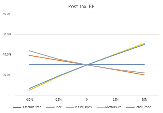
Source: Ausenco, July 2020
Figure 1-9 Post-Tax Sensitivity
At current spot prices, the after tax NPV and IRR are most sensitive to metal prices and least sensitive to initial capex and has approximately equal exposure to silver and gold prices. This information is shown in Table 1.12 and 1.13
Table 1‑12 Sensitivity to Metal Prices
Gold Price | Silver Price | After Tax | After Tax IRR |
1,200 | 12.00 | 49.8 | 14.2% |
1,400 | 14.00 | 107.8 | 24.2% |
Base Case | Base Case | 137.1 | 30.0% |
1,600 | 16.00 | 164.5 | 34.9% |
1,800 | 18.00 | 220.9 | 44.4% |
2,000 | 20.00 | 277.3 | 53.9% |
Table 1‑13 Sensitivity to CAPEX
Movement | OPEX NPV | OPEX IRR | Movement | CAPEX NPV | CAPEX IRR |
-20% | 173.2 | 36.2% | -20% | 150.4 | 38.1% |
-10% | 155.2 | 33.1% | -10% | 143.8 | 33.6% |
Base Case | 137.1 | 30.0% | Base Case | 137.1 | 30.0% |
10% | 118.9 | 26.7% | 10% | 130.4 | 26.9% |
20% | 100.7 | 23.4% | 20% | 123.7 | 24.3% |
1.21 Conclusions and Recommendations
1.21.1 Overall
The financial analysis of this UPFS demonstrates that the Terronera Project has robust economics to develop the project through feasibility and detailed engineering. Estimated costs for completing work recommended in Table 1-14.
Table 1-14 Budget Estimate for Completing the Recommended Work
Program Component | Cost Estimate ($M) |
Exploratory Drilling | 0.25 |
Mining – Mineral Resource and Reserve Estimate Updates | 0.5 |
Geomechanical Studies | 0.25 |
Site Geotechnical Studies | 0.20 |
Metallurgical Testing | 0.5 |
Hydrogeological Study | 0.15 |
TSF – Advance the design to construction level | 0.15 |
Environmental baseline studies and Social programs | 1.0 |
Optimization Studies | 0.3 |
Engineering Studies | 1.5 |
Total Cost | 4.80 |
1.21.2 Exploration
1.21.2.1 Drilling
Endeavour Silver should continue with the company’s infill and exploratory drill program strategies. Infill drilling should be orientated to investigate the continuity of silver-gold mineralisation both along strike and at depth to improve and further validate the confidence in the geological models being used for the deposits. Infill drilling should be considered to increase the volume and tonnage of the current deposits and advance the deposit knowledge toward higher levels of mineral resource classification.
Exploratory drilling should be used in collaboration with geophysical interpretations to test for mineralisation and potential expansion of both Terronera and La Luz deposits.
1.21.3 Mineral Resource Estimations
Based on the work completed for the Mineral Resource estimate, it is recommended that future Mineral Resource estimations further refine the constraining mineralised domains. Endeavour Silver should consider redefining the cut-off grade due to the low-cost mining method adopted and increase in metal prices.
1.21.4 Mineral Reserve and Mining Methods
The following recommendations are made for future mining studies:
• Explore opportunities to increase project value via reductions in planned mining loss and dilution and various ore control strategies:
o Explore impacts to the mine plan of re-blocking resource model
o Explore converting to a block percentage model and applying a manual dilution skin to mineralisation zones; further definition of mineralisation boundaries would be required to execute this strategy
o Explore the impacts of applying ore sorting technologies between the mine and mill
o Further work on comparing mining methods to evaluate costs versus ounces recovered
• Conduct additional hydrogeological fieldwork, including Packer testing, piezometer installation, and development of a 3D hydrogeological model for each deposit
• Execution of the following geotechnical work programs:
o Targeted geotechnical drilling at Terronera and La Luz deposits to increase data confidence for feasibility level engineering
o Ground-truthing of possible major structures
o Additional geomechanical testing leading to an updated Rock Mass Model
o Update the geotechnical models and perform advanced numerical modelling
o Geotechnical analysis of the foundations identified for Terronera and La Luz should be carried out to ensure suitability of site selections presented in this study
• Drill and blast testing to be carried out by drilling vendors and local explosives suppliers by analysing local rock types and conditions to assess the achievable drill penetration rates, optimal explosives mix and target powder factor for use in this operation
• Blasting for improved mine to mill performance can be optimised in future studies. Increased fragmentation can increase the grind capacity in the mill
• Further engagement with potential mining contractors, obtaining updated quotations for services
• Updates to detailed designs of the mines, infrastructure and external haul roads based on information gathered in the above studies
• Explore opportunities to increase project value via alternative deposit development strategies.
1.21.5 Metallurgical Testwork
A full feasibility study level metallurgical testwork program incorporating testwork on major lithological characterisation samples, variability samples, and production composite samples from both Terronera and La Luz deposits is recommended to provide further definition across the resource. Drill cores are available on site for the testwork and the sample selection program is currently in progress. Key recommendations include:
• Ore competency – Given the limited dataset for ore competency, additional JK Tech SMC tests (Axb) are recommended to be conducted over a range of rock types and spatial zones to define distribution and variability of ore competency; PQ core is recommended
• Ore hardness – RWi, BWi index tests should be conducted to define ore hardness distribution and variability
• Abrasion Index – Tests should be conducted to redefine the abrasion index
• Further testwork to optimize the grinding circuit
• Grade-recovery relationship – Flotation testing of additional samples at various grind sizes should be conducted to determine grade-recovery relationship
• Preconcentration – Evaluate preconcentration opportunities such as ore sorting to reduce operating costs and decrease cut-off grades
• Solid-liquid separation – Finalise the tailings deposition route based on optimised flowsheet conditions.
1.21.6 Recovery Methods
The following activities are recommended to support design of the processing plant beyond the UPFS and into the feasibility study:
• Geotechnical site investigations should be carried out at the preferred process plant site locations to characterise the foundation conditions associated with the proposed buildings
• Material flowability testwork should be completed to further develop the crushing and stockpile circuit design.
1.21.7 Site Infrastructure
The following activities are recommended to support the design of the site infrastructure beyond the UPFS and into the feasibility study:
• Geotechnical site investigations should be carried out at the preferred surface infrastructure site locations to characterise the foundation conditions associated with the proposed buildings
• The access road to site should be further analysed, reviewed and engineered, culminating in a detailed work package to be tendered to local contractors
• Alternate sources of power supply should be considered to decrease the footprint and earthworks required
• Conduct studies to define the source of water and requirements for water treatment.
1.21.8 Water Management
The following activities are recommended to support the design of the water management systems beyond the UPFS and into the feasibility study:
• Progress design of de-centralised water management in each complex consisting of sedimentation ponds, berms, drainage ditches and outlet channels
• Maintain adequate component waterbody setbacks to account for regulatory buffers and water management infrastructure
• Identify opportunities to enhance sedimentation pond volumes at select locations
• Continue geochemical testing and assessment of acid rock drainage/metals leaching (ARD/ML) to further refine parameters of potential concern
• Additional hydrogeological data should be collected to accurately estimate the underground pumping requirements
• Conduct a site-wide water balance and develop water disposal strategy to meet the environmental regulations.
1.21.9 Tailings Management Facility
The following activities are recommended to support the design of the tailings storage facility (TSF) beyond the PFS:
- Optimize TMF area design to minimize waste rock use and maximize its availability for underground mine backfill
- Conduct a materials handling conceptual tradeoff study between conveying and trucking options, and advance to feasibility level design the selected tailings transport option
- Consider additional land acquisition to optimize the TMF geometric design and allow for potential storage expansion.
1.21.10 Environmental, Permitting & Community Relations
A revised EIA application should be submitted to the Mexican environmental permitting authority known as SEMARNAT as per the revised production rate of 1,600 tpd.
2.1 Introduction
Ausenco Engineering Canada Inc. (Ausenco) prepared the Technical Report (the Report) for Endeavour Silver Corp. (Endeavour Silver) to summarise the results of an updated pre-feasibility study (UPFS) on the Terronera Silver Gold Project (the Terronera Project).
2.2 Terms of Reference
This Report supports disclosure by Endeavour Silver in a press release dated July 14, 2020, entitled « Endeavour Silver Announces Robust Economics in Final Pre-Feasibility Study on the Terronera Mine Project in Jalisco State, Mexico ».
Moose Mountain Technical Services (Moose Mountain), P&E Mining Consultants Inc. (P&E), JDS Consulting (JDS) and Wood plc (Wood) provided input to the report.
Mineral Resources and Mineral Reserves are reported in accordance with the Canadian Institute of Mining, Metallurgy and Petroleum (CIM) Definition Standards for Mineral Resources and Mineral Reserves (May 2014; the 2014 CIM Definition Standards).
2.3 Sources of Information
The following sources of information and data were used in preparing this Report:
• Personal inspections of the Terronera site and surrounding area
• Technical information provided by Endeavour Silver
• Information provided by other experts with specific knowledge in their fields as described in Section 3, Reliance on Other Experts
• Additional information obtained from public domain sources
• Documents listed in Section 27 References.
2.4 Qualified Persons
The Qualified Persons responsible for this Report are as follows:
• Robin Kalanchey, P.Eng., Director, Minerals & Metals – Western Canada, Ausenco
• Michael Petrina, P.Eng., Principle Mining Engineer, Moose Mountain
• Humberto Preciado, P.E, Senior Associate Geotechnical Engineer, Wood
• Euqene Puritch, P.Eng., F.E.C., CET, President, P&E Mining Consultants
• David Burga, P.Geo, Geologist, P&E Mining Consultants
• Yungang Wu, P.Geo, Geologist, P&E Mining Consultants
• Michael Levy, P.Eng., Geotechnical Manager, JDS Energy & Mining Inc.
• Eugenio Iasillo. P.E., Principal, Process Engineering LLC
2.5 Site Visits and Scope of Personal Inspection
Site visit dates and scope of personal inspection are as follows:
• Mr Humberto Preciado visited the site from December 11-14, 2015. During this time, he oversaw a portion of the geotechnical site investigation program in the proposed TSF, and the collection and submittal of waste rock samples to an analytical environmental laboratory in Mexico.
• Mr. Eugene Puritch visited the site on September 11, 2014. During that visit he inspected drilling sites, drill core, existing infrastructure, access roads, and potential mine portal and waste rock storage locations.
• Mr. David Burga visited the property on September 11, 2014; October 7, 2014; June 14, 2016, January 9 and October 16, 2018. While on site he reviewed representative drill core intervals from several holes at both deposits and observed ground conditions.
• Mr. Michael Levy visited the site from on October 8, 2020. While on site he reviewed representative drill core intervals from several holes at both deposits and observed ground conditions in two existing adits.
• Mr. Eugenio Iasillo visited the site on September 11 and 12, 2014. During this visit, Mr. Eugenio visited the drilling sites, drill core, existing infrastructure, access roads, and potential mine portal and waste rock storage locations.
2.6 Effective Dates
The Report has a number of effective dates as follows:
• Date of Mineral Resource estimate for the Terronera deposit: February 1, 2019
• Date of Mineral Resource estimate for the La Luz deposit: August 7, 2018
• Date of Mineral Reserve estimate: March 23, 2020
• Date of economic analysis that supports the Mineral Reserves: July 08, 2020
The overall Report effective date is the date of the cashflow that supports the Mineral Reserve estimates, and is July 14, 2020.
2.7 Previous Technical Reports
The following technical reports have previously been filed on the Terronera Project:
• Puritch, E., Robinson, D.G., Smith, P.J., Burga, D., Wu, Y., Iasillo, E., Preciado, H., and Peacock, B., 2019: Updated Technical Report for the Terronera Project, Jalisco State, Mexico: report prepared by P&E Mining Consultants Inc. for Endeavour Silver Corp., effective date February 12, 2019, 334 p.
• Puritch E., Burga, D., Wu, Y., Iasillo, E., and Preciado, H., 2019: Updated Mineral Resource Estimate Technical Report for the Terronera Project, Jalisco State. Mexico: report prepared by P&E Mining Consultants Inc. for Endeavour Silver Corp., effective date February 1, 2019, 230 p.
• Smith, P.J., Iasillo, E., Puritch, E., Wu, Y., Burga, D., Peacock, B., and Preciado, H., 2018: NI 43-101 and NI 43-101F1 Technical Report Updated Mineral Resource Estimate and Updated Preliminary Feasibility Study for the Terronera Project Jalisco State, Mexico: report prepared by Smith Foster and Associates for Endeavour Silver Corp., effective date 7 August, 2018, 317 p.
• Smith, P.J., Iasillo, E., Puritch, E., Wu, Y., Burga, D., Barry, J., Pearson, J., Peacock, B., and Fleming, S., 2017: NI 43-101 Technical Report Preliminary Feasibility Study for the Terronera Project Jalisco State Mexico: report prepared by Smith Foster and Associates for Endeavour Silver Corp., effective date April 3, 2017, 341 p.
• Smith, P.J., Iasillo, E., Puritch, E., Sutcliff, R., Burga, D., Barry, J., Routledge, R., Pearson, J., Peacock, B., and Fleming, S., 2015: NI 43-101 Technical Report Preliminary Economic Assessment for the Terronera Project, Jalisco State, Mexico: report prepared by Smith Foster and Associates for Endeavour Silver Corp., effective date March 25, 2015, 242 p.
Under the former project name of San Sebastian, the following technical reports were filed:
• Munroe, M.J., 2013: NI 43-101 Technical Report on the Resource Estimates for the San Sebastian Project, Jalisco State, Mexico: report prepared by Michael J. Munroe for Endeavour Silver Corp., effective date December 31, 2013, 140 p.
• Lewis, W.J., and Murahwi, C.Z., 2012: NI 43-101 Technical Report, Audit of the Mineral Resource Estimate for the San Sebastian Project, Jalisco State, Mexico: report prepared by Micon International Limited for Endeavour Silver Corp., effective date December 15, 2012, 128 p.
• Lewis, W.J., and Murahwi, C.Z., 2011: NI 43-101 Technical Report, Audit of the Mineral Resource Estimate for the San Sebastian Project, Jalisco State, Mexico: report prepared by Micon International Limited for Endeavour Silver Corp., effective date December 21, 2011, 131 p.
2.8 Units and Currency
All measurement units used in this report are metric unless otherwise noted. Currency is expressed in United States (US) dollars (US$). Contained silver metal is expressed as troy ounces (oz), where 1 oz = 28.3495 g. Contained gold metal is expressed as troy ounces (oz), where 1 oz = 31.1035 g. All material tonnes are expressed as dry tonnes
All currency amounts are stated in US dollars, or unless specified Mexican pesos (MXN). The exchange rate is based on a historical average at US$1.00 equal to MXN 20.0.
Quantities are generally stated in Système International d’Unités (SI) units, the standard Canadian and international practice. When applicable, any Imperial units of measure encountered have been converted to SI units for reporting consistency. Precious metal grades may be expressed in parts per million (ppm) and their quantities may also be reported in troy ounces (oz), a common practice in the mining industry. Base metal grades may be expressed as a percentage (%). Table 2-1 provides a list of the abbreviations used.
Table 2-1 Terminology and Abbreviations
Abbreviation | Name / Meaning |
$ | dollar |
% | percent |
$M | dollars, millions |
> | greater than |
< | less than |
‘ | foot |
« | inches |
° | degrees |
°C | degrees Celsius |
1/d3 | inverse distance cubed |
AA | atomic adsorption |
AAS | atomic absorption spectrometry |
Ag | silver |
AgEq | silver equivalent |
AGREMIN | Agregados Mineros de Occidente S.A. de C.V. |
ALS | ALS Metallurgy or ALS-Chemex or ALS Minerals or ALS laboratory |
Ai | bond abrasion index |
Au | gold |
BWi | bond ball mill work index |
CFE | Commission Federal de Electricidad or Comisión Federal de Electricidad |
CIM | Canadian Institute of Mining, Metallurgy and Petroleum |
CL | control limit |
Cm | centimeters |
CRM or standards | certified reference material or standard reference material |
CSA | Canadian Securities Administrators |
Cu | copper |
CUS | change of soils use |
CWi | bond impact work index testing |
DGM | Dirección General de Minas |
DTU | Unified Technical Document |
EIS | Environmental Impact Statement |
Endeavour Silver | Endeavour Silver Corporation |
Energold | Energold Drilling Corp. |
Energold Mexico | Energold de Mexico, S.A. de C.V. |
ETJ | Technical Economic Justification Study |
G | grams |
G&A | General and Administration |
g/t | grams per tonne |
H | height |
Ha | hectares |
HIG | high intensity grind |
HPGR | high pressure grinding rolls |
ICP | inductively coupled plasma |
ID | inverse distance |
IMMSA | Industrias Minera México S.A. de C.V. |
IRR | internal rate of return |
Kg | kilograms |
Koz | thousands of ounces |
KP | Knight Piésold Ltd. |
Kt | thousands of tonnes |
kt/y | thousands of tonnes per year |
kWh/t | kilowatt hours per tonne |
L | litres |
Layne | Layne de Mexico, S.A. de C.V. |
Layne Christensen | Layne Christensen Company |
LHD | load haul dump unit (scooptram) |
LL | lower control limit |
LNG | liquified natural gas |
LOM | life-of-mine |
M | meters |
M/a | million per annual |
M/y | million per year |
max. | maximum |
Mean | arithmetic average of group of samples |
Mg | milligrams |
MIA | Manifestación de Impacto Ambiental or Manifest of Environmental Impact |
MIA-P | Manifestación de Impacto Ambiental, particular modality |
min. | minimum |
Minera Cimarron | Minera Cimarron S.A. de C.V. |
Minera Plata | Minera Plata Adelante S.A. de C.V. |
Mm | millimeters |
MPA | Minera Plata Adelante S.A. de C.V. |
Mt | million tonnes |
MXN | Mexican pesos |
N/A or n/a | not available/applicable |
NE | northeast |
NI 43-101 | National Instrument 43-101 |
NN | nearest neighbor |
No. | number |
NPV | net present value |
NPV5% | net present value discounted at 5% |
NSR | net smelter return |
NW | northwest |
Oz | Troy ounces |
Pb | lead |
PFS | pre-feasibility study |
Ppb | parts per billion |
Ppm | parts per million (= g/t) |
Q | quarter |
QA | quality assurance |
QC | quality control |
QPs | Qualified Persons |
QMS | quality management system |
RWi | bond rod mill work index |
San Sebastián | San Sebastian del Oeste |
SD | Standard Deviation |
SE | southeast |
SEDENA | Secretaria de Seguridad Nacional |
SEMARNAT | Secretaria Medio Ambiente y Recursos Naturales |
SFA | Smith Foster & Associates Inc. |
SGS | SGS de México |
SOPs | standard operating procedures |
SPT | standard penetration testing |
Standards | standard reference material |
SW | southwest |
T | tonnes |
Tpd | tonnes per day |
TPM | Terronera Precious Metals S.A. de C.V. |
TMF | tailings management facility |
TSF | tailings storage facility |
UCF | unconsolidated rock fill |
U/G | underground |
UL | upper control limit |
UPFS | updated pre-feasibility study |
US$ or $ | United States dollars |
UTM | Universal Transverse Mercator grid system |
V | vertical |
VTR | vertical intensity grind |
W | width |
WGS 84 | World Geodetic System 1984 |
Yd | yard, imperial measurement |
YR | year |
Zn | zinc |
3 Reliance on Other Experts
3.1 Legal Status
The QPs have not independently reviewed the legal status of the Terronera Project. They have fully relied upon, and disclaim responsibility for, information derived from experts retained by Endeavour Silver for the legal status through the following report:
Cereceres Estudio Legal, S.C., 2020: prepared an internal report for Endeavour Silver by Mexico City-based Cereceres Estudio Legal, dated May 10, 2020
3.2 Baseline Studies, Environmental, and Permitting
The QPs have not independently reviewed the basis for, or the information in the baseline studies and application documents used to obtain the Manifestacion de Impacto Ambiental approvals for the Terronera Project. Humberto Preciado, P.E., of Wood, has fully relied upon the expert statements and representations submitted to SEMARNAT by:
• Ing. José Luis Razura González in the process of achieving the October 2014 SEMARNAT 500 tpd MIA permit for the Project, and,
• The statements and representations of Ing. Roberto Trujillo for the February 2017 1,500 tpd amended MIA permit.
• The statements and representations of Ruben Padilla for the MIA modification requirements and timeline to accommodate a production rate of 1,600 tpd.
Wood has not performed independent investigations to verify the reliability of the representations of Ing. Razura, Ing. Trujillo, Ruben Padilla and their respective consulting entities or associates. However, these are professionals with deep understanding of the environmental regulatory framework in Mexico who continue to work and consult with Endeavour Silver in their current operations.
The Trujillo study was submitted as MIA justification for the mine and process plant, and, as Wood is involved in only the tailings storage facility in the Mondeño area of the Project, Wood did not participate in the generation of or the environmental justification to regulatory authorities of the Trujillo study. Wood requested and received a copy of the Consultoría Forestal y Ambiental MIA report generated by Ing. Roberto Trujillo for the mine and plant components of the project in April 2017.
This information is used in Section 20 of the Report, and in support of the Mineral Resource estimate in Section 14, the Mineral Reserve estimate in Section 15, and the economic analysis in Section 22.
4 Property Description and Location
4.1 Location
The Terronera Project is located in the northwestern portion of Jalisco State, near its border with the State of Nayarit, Mexico as shown in Figure 1-1.
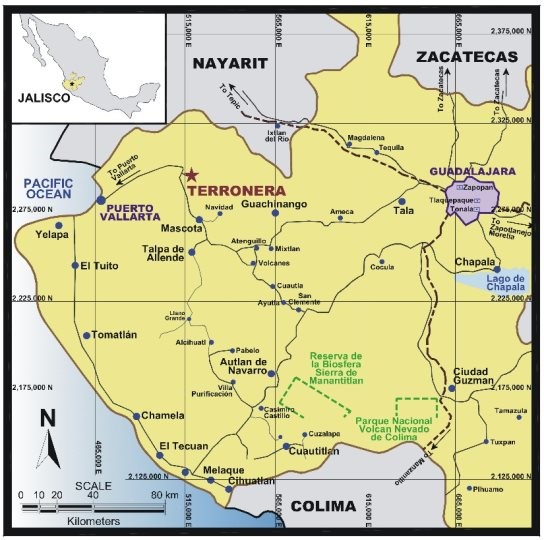
Source: Terronera NI43-101 Technical Report, April 30, 2019
Figure 4-1 Terronera Project Location Map
The Terronera Project is near the town of San Sebastián del Oeste, which also gives its name to the municipality and mining district which surrounds it.
The Terronera Project is situated between latitude 20° 39′ 45″ and 21° 02′ 30″ north and longitude 104° 35′ 00″ and 104° 51′ 00″ west which is between WGS 84, UTM coordinates 514,860 and 524,860 east and 2,303,715 and 2,289,120 north in Zone 13Q.
4.2 Mexican Regulations for Mineral Concessions
In Mexico, exploitation concessions are valid for 50 years and are extendable provided that the application is made within the five-year period prior to the expiry of the concession and the bi-annual fee and work requirements are in good standing. All new concessions must have their boundaries orientated north-south and east-west and the lengths of the sides must be one hundred meters or multiples thereof, except where these conditions cannot be satisfied if they border on other mineral concessions. The locations of the concessions are determined on the basis of a fixed point on the land, called the starting point, which is either linked to the perimeter of the concession or located thereupon. Prior to being granted a concession, the company must present a topographic survey to the Dirección General de Minas (DGM) within 60 days of staking. Once this is completed, the DGM will usually grant the concession.
Prior to December 21, 2005, exploration concessions in Mexico were granted for a period of six years and at the end of the six years they could be converted to exploitation concessions. However, as of December 21, 2005 (by means of an amendment made on April 28, 2005 to the Mexican mining law) there is now only one type of mining concession. Therefore, as of the date of the amendment (April 2005), there is no distinction between exploration and exploitation concessions on all new titles granted.
All concessions are now granted for a 50 year period provided that the concessions are kept in good standing. For the concessions to remain in good standing, a bi-annual fee must be paid (January and July) to the Mexican government and two reports must be filed in January and May of each year that cover the production and work completed on the concession between January and December of the preceding year.
4.3 Property Description and Tenure
In February, 2010, Endeavour Silver acquired an option to purchase the San Sebastián concessions in Jalisco State from Industrias Minera México S.A. de C.V. (IMMSA), also known as Grupo Mexico, one of the largest mining companies in Mexico.
Endeavour Silver holds the Terronera Project through its 100% owned Mexican subsidiary, Endeavour Gold Corporation S.A. de C.V. (Endeavour Gold). Endeavour Gold holds the Terronera Project through its 100% owned subsidiaries Terronera Precious Metals S.A. de C.V. (TPM) and Minera Plata Adelante S.A. de C.V. (MPA).
The Terronera Project consists of 24 mineral concessions (Table 4-1), totalling 17,369 ha; see Figure 4-2 for a concession map of the Terronera Project.
Table 4-1 Concessions and Taxes on Each Concession
Concession Name | Title Number | Term of Mineral Concession | Hectares | 2020 Annual Taxes (MXN) | |
1st Half | 2nd Half | ||||
San Sebastián 4 | 211073 | 31/03/00 to 30/03/50 | 22.0000 | $3,755 | $3,755 |
San Sebastián 7 | 213145 | 30/03/01 to 29/03/51 | 166.0000 | $28,268 | $28,268 |
San Sebastián 6 | 213146 | 30/03/01 to 29/03/51 | 9.8129 | $1,680 | $1,680 |
Concession Name | Title Number | Term of Mineral Concession | Hectares | 2020 Annual Taxes (MXN) | |
1st Half | 2nd Half | ||||
San Sebastián 8 | 213147 | 30/03/01 to 29/03/51 | 84.8769 | $14,459 | $14,459 |
San Sebastián 5 | 213528 | 18/05/01 to 17/05/51 | 95.0600 | $16,192 | $16,192 |
San Sebastián 10 | 213548 | 18/05/01 to 17/05/51 | 16.0000 | $2,734 | $2,734 |
San Sebastián 9 | 214286 | 06/09/01 to 05/09/51 | 101.8378 | $17,346 | $17,346 |
San Sebastián 2 | 214634 | 26/10/01 to 25/10/51 | 19.5887 | $3,345 | $3,345 |
San Sebastián 3 | 221366 | 03/02/04 to 02/02/54 | 63.8380 | $10,877 | $10,877 |
San Sebastián 1 R-1 | 235753 | 24/02/10 to 07/07/55 | 2808.8716 | $478,164 | $478,164 |
San Sebastian 10 Fracc. 1 | 238532 | 23/09/11 to 22/09/61 | 2075.2311 | $200,747 | $200,747 |
San Sebastian 10 Fracc. 2 | 238533 | 23/09/11 to 22/09/61 | 2.9233 | $293 | $293 |
San Sebastian 17 | 243380 | 12/09/14 to 11/09/64 | 693.0000 | $33,530 | $33,530 |
San Sebastian 18 | 244668 | 17/11/15 to 16/11/65 | 118.1621 | $2,852 | $2,852 |
San Sebastian 12 | 246040 | 20/12/17 to 19/12/67 | 650.0000 | $7,570 | $7,570 |
San Sebastian 13 | 246037 | 20/12/17 to 19/12/67 | 1022.6114 | $11,903 | $11,903 |
San Sebastian 14 | 246084 | 20/12/17 to 19/12/67 | 627.0893 | $7,303 | $7,303 |
Cerro Gordo 1 | 246334 | 11/05/18 to 10/05/68 | 499.7041 | $5,822 | $5,822 |
Cerro Gordo 2 | 246335 | 11/05/18 to 10/05/68 | 500.0000 | $5,825 | $5,825 |
Cerro Gordo 4 | 246713 | 31/10/18 to 30/10/68 | 400.0000 | $4,662 | $4,662 |
Cerro Gordo 5 | 246714 | 31/10/18 to 30/10/68 | 399.5386 | $4,657 | $4,657 |
Concession Name | Title Number | Term of Mineral Concession | Hectares | 2020 Annual Taxes (MXN) | |
1st Half | 2nd Half | ||||
Los Pinos Fracc. I | 227004 | 11/04/06 to 10/04/56 | 4821.6775 | $820,804 | $820,804 |
Los Pinos Fracc. II | 227005 | 11/04/06 to 10/04/56 | 14.0093 | $2,395 | $2,395 |
La Unica Fracc. I | 225184 | 02/08/05 to 01/08/55 | 2157.2787 | $367,244 | $367,244 |
Total |
|
| 17,369.1113 | $2,052.427 | $2,052.427 |
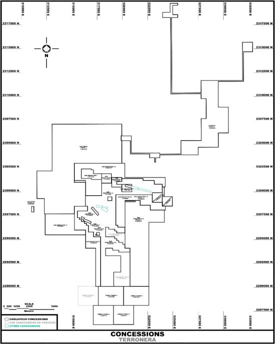
Source: Terronera NI43-101 Technical Report, April 30, 2019
Coordinate system: WGS 84 / UTM Zone 13Q
Figure 4-2 Terronera Project Concessions Map
The core group of 10 concessions was owned by IMMSA, totalling 3,388 ha. These concessions cover the main area of the known mining district. In 2013, Endeavour Silver completed the acquisition of a 100% interest in the San Sebastián concessions from IMMSA.
In 2012, Endeavour Silver also filed and received title for two concessions (San Sebastián 10 Fracc. 1 and Fracc. 2) totalling 2,078 ha.
Additionally, in 2013, Endeavour Silver filed a total of seven concessions (San Sebastian 12, San Sebastian 13, San Sebastian 14, San Sebastian 15, San Sebastian 16, San Sebastian 17 and San Sebastian 18) totalling 4,163 ha. To date, five of these concessions have been titled, with the exception of San Sebastian 15 and San Sebastian 16, which were re-filed in November and August 2018 respectively.
In 2015, Endeavour Silver acquired an option to purchase a group of properties (Los Pinos Fracc. I, Los Pinos Fracc. II and La Fundisión 2 Fracc. I, totalling 8,373 ha), surrounding the San Sebastián silver-gold properties, from Agregados Mineros de Occidente S.A. de C.V. (AGREMIN). In 2017 Endeavour Silver also acquired another option from AGREMIN to purchase the La Única Fracc. II (3,538 ha) concession. These properties and the options agreement were transferred by AGREMIN to its affiliate, Compañia Plata San Sebastian S.A. de C.V. On December 2018 Endeavour Silver terminated the option agreement for La Fundision 2 Fracc. I (Title 228866) and La Única Fracc. II (Title 225185) concessions and cancellation is currently in process.
At the end of 2017, Endeavour Silver filed for a total of three concessions at the southern boundary of the San Sebastian Properties, these concessions were called Cerro Gordo 1 (499.7 ha), Cerro Gordo 2 (500 ha) and Cerro Gordo 3 (400 ha). Two of these concessions have been titled, with the exception of Cerro Gordo 3 (filed again in June of 2018). In early 2018, Endeavour Silver filed and received title for two more concessions in the area: Cerro Gordo 4 (400 ha) and Cerro Gordo 5 (399 ha).
In August 2018, Endeavour Silver acquired an exploration and option agreement covering the La Unica Fracc. I (2157 ha) property from Compañia Plata San Sebastian S.A. de C.V.
The annual 2020 concession tax for the Terronera project was MXN 4,104,854 which is equal to US$205,243 (at an exchange rate of 20 MXN to US$1.00). Confirmation of payment and statutory reporting was received in the May 10, 2020 title opinion by Cereceres Estudio Legal, S.C.
The Endeavour Silver concessions surround mining concessions owned by Minera Cimarron S.A. de C.V. (Minera Cimarron), a private Mexican Company. These concessions cover the active La Quiteria Mine, and the historic Los Reyes and San Andres mines. These concessions were included in Figure 4-2.
4.4 Surface Rights
In addition to the mineral rights, Endeavour Silver has agreements with various private ranch owners and three local Ejidos (San Sebastián del Oeste, Santa Ana and Santiago de Los Pinos) that provide access for exploration purposes. Table 4-2 summarizes the surface access rights as at July 21, 2020.
Table 4-2 Summary of Endeavour Silver’s Surface Access Rights
Owner | Activity | Validity | Term |
Ejido Santiago de Los Pinos (Exploration) | Exploration | 3 Years | 15/01/2019 – 2022 |
Ejido San Felipe de Hijar (Exploration) | Exploration | 5 Years | 15/01/2019 – 2024 |
Ejido San Sebastian | Exploration & Operations | 25 Years | 05/09/2016 – 2041 |
Ejido Santiago de Los Pinos | Mine Operations | 25 Years | 07/07/2014 – 2039 |
Ejido Santiago de Los Pinos | Mine Operations | 25 Years | 07/07/2014 – 2039 |
Ejido Santiago de Los Pinos | Mine Operations | 25 Years | 27/04/2015 – 2040 |
Ejido Santiago de Los Pinos (Antenas; Telecomunicaciones) | Mine Operations | 15 Years | 09/08/2016 – 2031 |
Felipe Santana García de Alba (Telecomunicaciones) | Mine Operations | 3 Years | 15/07/2016 – 2022 |
4.5 Water Rights
The Mexican Mining Law states in Article 19 that mining concessions give the right to exploit the water coming from the mine for exploration, exploitation and processing of the minerals or substances obtained and for personal in the project; therefore, a groundwater use concession title is not required, if the supply is guaranteed by mine water.
4.6 Royalties and Encumbrances
IMMSA retains a 2% NSR royalty on mineral production from the San Sebastián concessions. In addition to that, a 0.5% royalty is retained by the government for production of precious metals.
4.7 Permitting Considerations
Permitting is discussed in Section 20.
4.8 Environmental Considerations
The Terronera Project will be a greenfield mine development. Current and past land use has been for agriculture, grazing and forestry purposes. Environmental disturbances for these historical uses include road construction, cattle corrals, and other small farming structures.
Based on surface disturbance, other than the historical adits, no historical mining activities appear to have occurred within the project boundaries. Currently, site disturbance has been limited to mining exploration drilling within La Luz and Terronera mining areas. These areas represent small footprints around the exploration boreholes that are remediated and reclaimed shortly after the drilling campaign is completed. Therefore, being a greenfields mining project, current environmental liabilities of Endeavour Silver are low and limited to localized exploration-disturbed areas.
4.9 Social License Considerations
Social license considerations are discussed in Section 20.
4.10 QP Comments on « Item 4; Property Description and Location »
The QP notes:
• Mineral concessions are valid and in good standing
• IIMSA retains a 2% NSR royalty on mineral production from the San Sebastián concessions
• Government retains a 0.5% royalty on precious metals produced
• Surface rights and access rights have been negotiated with various private ranch owners and three local ejidos in support of exploration activities. Surface rights to support mining operations remain to be negotiated
• The Mexican Mining law provides the right to use water from the mine for exploration, exploitation, processing and for personnel in the project; therefore, a groundwater use concession title is not required.
To the extent known to the QP, there are no other significant factors and risks that may affect access, title or right or ability to perform work on the Project that are not discussed in this Report.
5 Accessibility, Climate, Local Resources, Infrastructure and Physiography
5.1 Accessibility
The Terronera Project is situated approximately 160 km due west of Guadalajara in Jalisco State and 50 km northeast of Puerto Vallarta. Road access is via paved roads. From Guadalajara, travel by road is via Federal Highway No. 70 that passes through the town of Mascota, about 210 km west of Guadalajara, and then it is another 55 km to San Sebastián del Oeste. Highway 70 continues to Puerto Vallarta on the Pacific coast. Good gravel roads exist within the Terronera Project area, and year-round access is possible, although some difficulties may be experienced during the rainy season.
Recent road improvements have reduced the road transit time from Puerto Vallarta to San Sebastián del Oeste to less than two hours. San Sebastián del Oeste is also served by a paved airfield in excellent condition.
National and international access to Puerto Vallarta and Guadalajara is quite good, with numerous daily flights from major cities in Mexico, the United States and Canada, giving many options for travelling to and from the Terronera Project.
5.2 Local Resources and Infrastructure
The municipality of San Sebastián del Oeste has a population of approximately 5,600 with less than 1,000 living in the town of the same name. The town of San Sebastián del Oeste is well maintained, and tourism is the principal industry with several hotels and restaurants. It receives regular tourist visits from nearby Puerto Vallarta.
Most of the labour and small equipment required for exploration programs can be found in the municipality of San Sebastián del Oeste. Supplies are usually purchased in Puerto Vallarta, Mascota, or Guadalajara.
Additional information on local resources and infrastructure envisaged in the UPFS is provided in Section 18.
5.3 Climate
The climate type reported for the Terronera Project site is subtropical with the rainy season occurring from June to September. July is typically the wettest month. The weather is predominantly humid in the winter and dry and warm during the spring. The mean annual temperature is 18°C, with a maximum of 25.6°C and a minimum of 11.7°C. Prevailing winds in the area are from the southwest.
Exploration activities can be curtailed by wet weather. It is envisaged that any future mining operations will be conducted on a year-round basis.
5.4 Physiography
The Terronera Project is located in a mountainous region of Western Mexico with elevations ranging from sea level at the Pacific coast to 2,850 m in the highest elevation in the San Sebastian region of the Sierra Madre Occidental mountain range. The town of San Sebastián del Oeste is at an elevation of 1,480 m above sea level.
Elevations range from 1,160 m to 1,800 m within the Terronera Project footprint.
The surrounding area is mountainous and heavily forested, mainly with pine trees. The surrounding valleys are occupied by cattle ranches, corn fields and coffee plantations.
5.5 Infrastructure
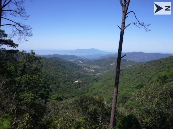
Source: www.edrsilver.com, Dated July 08, 2020.
Figure 5-1 View of Topography Surrounding the Town of San Sebastián
6.1 San Sebastian Del Oeste Mining District
The following section is summarized from Lewis and Murahwi (2012) and Munroe (2013). San Sebastián del Oeste is a silver and gold mining town founded in 1605 during the Spanish colonial period. By 1785, more than 25 mines and a number of smelters had been established in the district and, during the peak mining period, the area was considered one of the principal sources of gold, silver and copper for New Spain. The main mines in the district included Real de Oxtotipan, Los Reyes, Santa Gertrudis, Terronera and La Quiteria.
San Sebastián del Oeste was declared a city in 1812 and reached a peak population of more than 20,000 people by 1900. At one time, it was the provincial capital and one of the more important gold and silver mining centres of Mexico. The prosperity of the city declined after the revolution of 1910.
The mines were, in part, responsible for the founding of the city of Puerto Vallarta that supplied those mines with salt. The salt was taken by mules to San Sebastián del Oeste and other mines in the high sierras for use in the metal smelting process. The silver and gold from the mines were sent, again by mule train, through Guadalajara and Mexico City to Veracruz, where it was sent to Spain.
Exploration activities, where known, are summarized in Table 6-1.
Table 6-1 Exploration History Summary
Year | Company | Exploration |
1921 | Various, unknown | After the Mexican Revolution, intermittent small scale mining took place in the areas of Santiago de Los Pinos, Los Reyes and Navidad. All of these areas are currently inactive. |
1979 | Consejo de Recursos Minerales | Regional and local semi-detailed mapping and exploration activity. |
1985 | Compañía Minera Bolaños, S.A. | Prospecting activities in the areas of Los Reyes and Santiago de Los Pinos. This work eventually ended and many of the concessions were allowed to elapse. |
Late 1980s | IMMSA | Exploration begins in Sebastián del Oeste district. |
1992 – 1995 | IMMSA | Detailed geological mapping and sampling of outcropping structures including the La Quiteria, San Augustin and Los Reyes veins, as well as other veins of secondary importance. IMMSA assayed more than 200 rock samples from many of the old mines. |
1995 – 2010 | IMMSA | An initial program of 17 widely-spaced diamond drill holes was completed, mainly at the Terronera Vein. Drilling succeeded in intersecting widespread silver- gold mineralization generally ranging up to 1 g/t gold and from 50 to 150 g/t silver over 2 to 6 m widths. Drilling was suspended and quantification of mineral resources was not undertaken. |
2010 | Endeavour Silver / IMMSA | Endeavour Silver acquires option to purchase San Sebastián properties from IMMSA. |
2010 | Endeavour Silver | Data compilation, geological mapping, rock chip and soil sampling. |
2011 | Endeavour Silver | Geological mapping, rock chip sampling, topographic surveying. Core drilling (36 holes; 7,688.25 m). Resource estimate. |
2012 | Endeavour Silver | Core drilling (32 holes; 13,237.1 m). Updated resource estimate. |
2013 | Endeavour Silver | Geological mapping, trenching, rock chip and trench sampling. Core drilling (30 holes; 8,573.5 m). Updated resource estimate. |
2014 | Endeavour Silver | Geological mapping, trenching, rock chip and trench sampling. Core drilling (27 holes; 8,204.20 m). |
2015 | Endeavour Silver | Geological mapping, trenching, soil and trench sampling. Core drilling (27 holes; 6,133 m. Updated resource estimate. Preliminary economic assessment. |
2016 | Endeavour Silver | Reconnaissance exploration, rock chip and soil sampling. Core drilling (19 holes; 5,670 m). |
2017 | Endeavour Silver | Geological mapping, trenching, rock chip and trench sampling. Core drilling (47 holes; 2,252 m). Updated resource estimate. Pre-feasibility study. First-time declaration of Mineral Reserves. |
2018 | Endeavour Silver | Core drilling (39 holes; 18,774 m). Updated resource estimate. |
2019 | Endeavour Silver | Updates to mine design and production schedule from 2017 pre-feasibility study |
2020 | Endeavour Silver | UPFS |
6.2 Previous Mineral Resource and Mineral Reserve Estimates
Lewis and Murahwi (2013) of Micon conducted an audit of Endeavour Silver’s Mineral Resource Estimates at the Terronera Project (then called the San Sebastián Project) including the Animas-Los Negros, El Tajo, Real and Terronera Veins. As of December 15, 2012, the estimate for the San Sebastian Project comprised Indicated Mineral Resources totalling 1,835,000 t at a grade of 193 g/t Ag and 1.17 g/t Au and Inferred Mineral Resources of 3,095,000 t at a grade of 196 g/t Ag and 1.39 g/t Au. The Terronera Vein is the largest component of the estimate and was estimated to contain Indicated Mineral Resources of 1,528,000 t at 192 g/t Ag and 1.30 g/t Au and Inferred Mineral Resources of 2,741,000 t at 194 g/t Ag and 1.50 g/t Au. The San Sebastian estimate utilized a 2-D polygonal estimation method for the Animas-Los Negros, El Tajo, and Real veins and 3-D block modelling for the Terronera Vein. Samples were capped at 524 g/t Ag and 2.38 g/t Au for the Animas-Los Negros, El Tajo, and Real Veins and 1,970 g/t Ag and 7.96 g/t Au for the Terronera Vein. The estimate utilized a bulk density of 2.5 t/m3 for all veins and a cut-off grade of 100 g/t AgEq based on metal prices of US$31/oz Ag and US$1,550/oz Au.
Munroe (2014) updated the San Sebastian Project Mineral Resource Estimate with additional drilling data. As of December 31, 2013, Munroe (2014) estimated the San Sebastian Project including the Animas-Los Negros, El Tajo, Real and Terronera Veins to contain Indicated Mineral Resources totalling 2,476,000 t at a grade of 229 g/t Ag and 1.08 g/t Au and Inferred Mineral Resources of 2,376,000 t at a grade of 175 g/t Ag and 1.66 g/t Au. The Terronera Vein was estimated to contain Indicated Mineral Resources of 2,169,000 t at 233 g/t Ag and 1.16 g/t Au and Inferred Mineral Resources of 2,022,000 t at 169 g/t Ag and 1.86 g/t Au. Munroe’s parameters were similar to those reported for Lewis and Murahwi (2013), except that the sample capping values were increased in the Terronera Vein to 2,070 g/t Ag and 7.96 g/t Au and the cut-off grade of 100 g/t AgEq was based on metal prices of US$24.20/oz for Ag and US$1,452/oz for Au.
The reader is cautioned that P&E has not verified the Lewis and Murahwi (2013) and Munroe (2014) Mineral Resource Estimates relating to the Terronera Project (formerly known as the San Sebastian Project).
In 2015, P&E updated the Terronera Project Mineral Resource Estimate. As of April 30, 2015, the Terronera Vein was estimated to contain Indicated Mineral Resources of 2.9 Mt at 211 g/t Ag and 1.65 g/t Au and Inferred Resources of 1.2 Mt at 218 g/t Ag and 1.39 g/t Au. The cut-off grade was 100 g/t AuEq, using a 70:1 ratio based on prices of US$18/oz silver and US$1,250/oz gold.
In 2017, P&E updated the Terronera Project Mineral Resource Estimate. As of May 11, 2017, the Terronera Vein was estimated to contain Indicated Mineral Resources of 3,959,000 t at 232 g/t Ag and 2.18 g/t Au and Inferred Mineral Resources of 720,000 t at 309 g/t Ag and 1.48 g/t Au. The cut-off grade was 150 g/t AgEq, using a 70:1 ratio based on US$18/oz silver and US$1,225/oz gold.
In August 2018, P&E updated the Terronera Project Mineral Resource Estimate again. As of August 7, 2018, the Terronera Vein was estimated to contain Indicated Mineral Resources of 4,363,000 t at 239 g/t Ag and 2.53 g/t Au and Inferred Mineral Resources of 1,073,000 t at 252 g/t Ag and 2.38 g/t Au. The cut-off grade was 150 g/t AgEq, using a 75:1 ratio based on US$17/oz silver and US$1,275/oz gold.
The February 2019 Mineral Resource and Mineral Reserve estimates reported in Sections 14 and 15 of this Updated Technical Report supersedes all prior Mineral Resource and Mineral Reserve estimates.
An Initial pre-feasibility study (PFS) was published on the Terronera Project in April 2017 resulting in a Probable Mineral Reserve of 4,061,000 t at 207 g/t Ag and 1.95 g/t Au. The financial model generated a post-tax 21.2% internal rate of return (IRR), 4.3 year payback and an net present value (NPV)5 of $78.1 M.
A second pre-feasibility study was published on the Terronera Project in September 2018 resulting in a Probable Mineral Reserve of 4,701,000 t at 224 g/t Ag and 2.28 g/t Au. The financial model generated a post-tax 23.5% IRR, 5.4 year payback and an NPV5 of $117.8 M.
A third Technical Report was published on the Terronera Project in April 2019 resulting in a Probable Mineral Reserve of 5,587,000 t at 208 g/t Ag and 2.33 g/t Au. The financial model generated a post-tax 23.8% IRR, 3.5 year payback and an NPV5 of $103.0 M.
6.3 Past Production History
There has reportedly been significant historical production from the San Sebastian del Oeste region spanning the period from 1566 when the Villa de San Sebastian was founded through to the early 20th century. The amount of silver production, however, is unknown since historical production records have not survived the revolutions, passing of the individual owners, closing of the mines, corporate failure, or government seizure of assets (Lewis and Murahwi (2012), Munroe (2013)).
7 Geological Setting and Mineralization
7.1 Regional Geology
The following section is summarized from Lewis and Murawhi (2012) and Munroe (2013). The mining district of San Sebastián del Oeste, shown in Figure 7-1, is situated at the southern end of the Sierra Madre Occidental metallogenic province, a north-northwesterly trending volcanic belt of mainly Tertiary age. This volcanic belt is more than 1,200 km long and 200 to 300 km wide and hosts the majority of Mexico’s gold and silver deposits. The volcanic belt is one of the world’s largest epithermal precious metal systems.
The oldest rocks in the southern part of the Sierra Madre Occidental are late-Cretaceous to early-Tertiary calc-alkaline, granodiorite to granite batholiths that intrude coeval volcano-sedimentary units of late Eocene to Miocene age.
The Terronera Project lies within the structurally and tectonically complex Jalisco Block at the western end of the younger (early Miocene to late Pliocene) Trans-Mexican Volcanic Belt. Country rocks within the Jalisco Block include Cretaceous silicic ash flows and marine sedimentary rocks deposited between 45 and 115 Ma that are intruded by Cretaceous to Tertiary granite, diorite and granodiorite of the Puerto Vallarta Batholith. The volcanic rocks of the San Sebastián cinder cone field are dated at 0.48 to 0.26 Ma, and are characterized by distinct, high potassium, alkalic compositions and were extruded within the Tepic-Zacoalco Graben that bounds andesitic stratovolcanoes located to the north and northeast.
The area has been affected by strong tectonic activity during the Cretaceous to Recent period, which has resulted in regional northwest-southeast striking transcurrent faults associated with movements of the northern portion of the Jalisco Block.
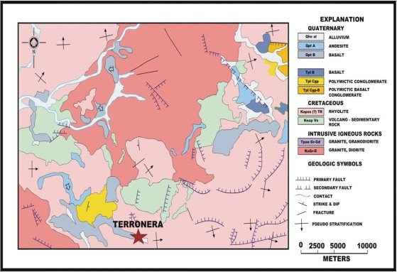
Source: Lewis and Murahwi, 2013
Figure 7-1 Geology of the San Sebastián del Oeste Area
7.2 Local Geology
The San Sebastián del Oeste area, including the Terronera Project, is underlain by an intermediate to felsic volcanic and volcaniclastic sequence that is correlated with the middle to lower Cretaceous Lower Volcanic Group of the Sierra Madre Occidental geological province. This volcano-sedimentary sequence consists of shale, sandstone and narrow calcareous-clayey interbeds overlain by tuffs, volcanic breccias and lava flows of mainly andesitic composition. The volcano-sedimentary units crop out in the north-central part of the district. Further to the north, granitic to granodioritic intrusive rocks are present.
The sedimentary basin most likely developed along with a volcanic arc which was later intruded by granitic granodiorite intrusions. This magmatism gave rise to andesite flows and pyroclastic eruptions followed by deposition of the rhyolite flows, volcanic breccias, pyroclastic dacites, and basalt which are host to the epithermal veins in the district. A later volcanic event, attributable to the formation of the Trans Mexican Volcanic Belt, resulted in volcanic rocks of mafic alkaline composition. The geology of Terronera Project area is shown in Figure .
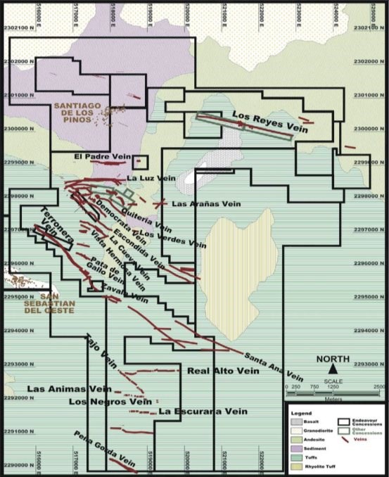
Source: Endeavour Silver, 2015
Coordinate system: WGS 84 / UTM Zone 13Q
Figure 7-2 Terronera Project Geology Showing Mineralized Veins
7.3 Deposit Geology
The silver-gold with associated base metal mineralization in the Terronera epithermal veins occurs in structurally controlled quartz and quartz breccia veins. The principal Terronera Vein has been traced by drilling for 1.5 km on strike and from surface to the maximum depth of drilling at 546 m as shown in Figure . The Terronera Vein strikes at approximately 145° and dips 80° east. The true width of the principal Terronera Vein ranges from 1.5m to 15m and averages 3.9m. In addition to the main Terronera Vein, there are additional hanging wall and footwall veins. The veins are primarily hosted in volcanic flows, pyroclastic and epiclastic rocks and associated shales and their metamorphic counterparts (Lewis and Mulahwi (2013), Munroe (2014)).
7.4 Structure
The more important mineralized veins in the San Sebastián del Oeste district are controlled by west-northwest to northwest striking structures related to a transcurrent fault system. An extensive, second order, east-west structural trend is related to extension caused by sinistral movement on the primary structures.
7.5 Alteration
In the San Sebastián del Oeste district, silver and gold mineralization represents the upper portion of an epithermal vein system. Illite, sericite and adularia are characteristic alteration assemblages that typically occur in the veins and in the vein wall rocks. In areas of higher elevation, where limited mining has occurred, such as the El Hundido and Real de Oxtotipan mines, the quartz is amorphous and milky white in colour, indicative of a low temperature environment.
7.6 Mineralization
The silver-gold ± base metal mineralization in the epithermal veins is hosted in structurally controlled quartz and quartz breccia veins. In addition to the main Terronera Vein, there are additional hanging wall and footwall veins. The veins are primarily hosted in volcanic flows, pyroclastic and epiclastic rocks and associated shales and their metamorphic counterparts.
Metallic minerals include galena, argentite, and sphalerite associated with gangue constituents of quartz, calcite and pyrite. Munroe (2013) reported that elevated Ag and Au values from 2011 sampling of underground workings in the Terronera Vein were primarily obtained from crystalline quartz veins, drusy in places, with limonite and manganese oxides lining boxworks after sulphides and fine-grained disseminated pyrite and traces of dark grey sulphides, probably silver sulphides.
Regionally, known deposits contain polymetallic sulphide mineralization in wide vein structures. The veins at higher elevations may represent the tops of ore shoots containing significant silver and gold mineralization at depth.
The deposits within the San Sebastián del Oeste district are considered to be examples of low-sulphidation epithermal deposits.
8.1 Low-Sulphidation Epithermal Deposits
The following description for low-sulphidation epithermal model is taken from Pantaleyev (1996).
8.1.1 Geological Setting
Low-sulphidation epithermal deposits are formed by high-level hydrothermal systems from depths of ~1 km to surficial hotspring settings. Deposition is related to regional-scale fracture systems related to grabens, (resurgent) calderas, flow-dome complexes and rarely, maar diatremes. Extensional structures in volcanic fields (normal faults, fault splays, ladder veins and cymoid loops, etc.) are common; locally graben or caldera-fill clastic rocks are present. High-level (subvolcanic) stocks and/or dikes and pebble breccia diatremes occur in some areas. Locally resurgent or domal structures are related to underlying intrusive bodies.
Most types of volcanic rocks can host the deposit type; however, calcalkaline andesitic compositions predominate. Some deposits occur in areas with bimodal volcanism and extensive subaerial ashflow deposits. A less common association is with alkalic intrusive and shoshonitic volcanic rocks. Clastic and epiclastic sediments can be associated with mineralization that develops in intra-volcanic basins and structural depressions.
8.1.2 Mineralization
Ore zones are typically localized in structures, but may occur in permeable lithologies. Upward-flaring ore zones centred on structurally controlled hydrothermal conduits are typical. Large (> 1 m wide and hundreds of meters in strike length) to small veins and stockworks are common with lesser disseminations and replacements. Vein systems can be laterally extensive, but ore shoots have relatively restricted vertical extent. High-grade ores are commonly found in dilational zones in faults at flexures, splays and in cymoid loops.
Textures typical of low-sulphidation deposits include open-space filling, symmetrical and other layering, crustification, comb structure, colloform banding and multiple brecciation.
Deposits can be strongly zoned along strike and vertically. Deposits are commonly zoned vertically over 250-350 m from a base metal poor, gold-silver-rich top to a relatively silver-rich base metal zone and an underlying base metal-rich zone grading at depth into a sparse base metal, pyritic zone. From surface to depth, metal zones can contain: gold-silver-arsenic-antimony-mercury, gold-silver-lead-zinc-copper, or silver-lead-zinc. In alkalic host rocks, tellurides, vanadium-mica (roscoelite), and fluorite may be abundant, with lesser molybdenite.
Pyrite, electrum, gold, silver, argentite; chalcopyrite, sphalerite, galena, tetrahedrite, silver sulphosalt and/or selenide minerals are the main mineral species. Quartz, amethyst, chalcedony, quartz pseudomorphs after calcite, calcite; adularia, sericite, barite, fluorite, calcium-magnesium-manganese-iron carbonate minerals such as rhodochrosite, hematite, and chlorite are the most common gangue minerals.
8.1.3 Alteration
Silicification is extensive in ores as multiple generations of quartz and chalcedony are commonly accompanied by adularia and calcite. Pervasive silicification in vein envelopes can be flanked by sericite-illite-kaolinite assemblages. Intermediate argillic alteration (kaolinite-illite-montmorillonite (smectite)) can form adjacent to some veins; advanced argillic alteration (kaolinite-alunite) may form along the tops of mineralized zones. Propylitic alteration dominates peripherally and at depth.
Figure illustrates the spatial distribution of the alteration and veining found in a hypothetical low-sulphidation hydrothermal system.
8.2 Applicability of the Low-Sulphidation Model to the Terronera Project
Low-sulphidation epithermal veins in Mexico typically have a well-defined, subhorizontal ore horizon about 300 m to 500 m in vertical extent where bonanza grade mineralization shoots have been deposited due to boiling of hydrothermal fluids. Neither the top nor the bottom of the mineralized horizons at the Terronera Project has been precisely established.
The San Sebastián del Oeste silver-gold district hosts high grade silver-gold, epithermal vein deposits, characterized by low-sulphidation mineralization and adularia-sericite alteration. The veins are typical of epithermal silver-gold vein deposits in Mexico in that they are primarily hosted in volcanic flows, pyroclastic and epiclastic rocks, or sedimentary sequences of shale and its metamorphic counterparts.
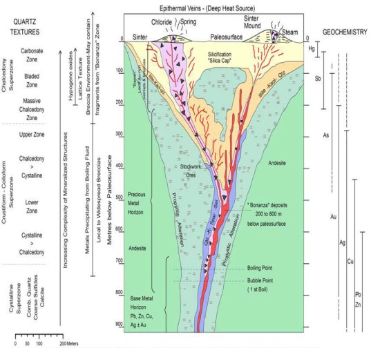
Source: Lewis and Murahwi, 2012
Figure 8-1 Alteration and Mineralization Distributions within a Low Sulphidation Epithermal Vein System
8.3 QP Comments on « Item 8: Deposit Types »
The QP is of the opinion that exploration programs that use a low sulphidation deposit model are applicable to the Terronera Project area.
9.1 Grids and Surveys
The topographical and geographical mapping basis for the Terronera Project uses satellite photogrammetry taken on March 1, 2012 by Photosat Satellite and GIS Data Consultant of Vancouver, Canada. The topographic resolution for these data generated 1 m contours. Because the project area has remained relatively undisturbed since the date of this satellite capture, the image and contour data are used as the basis of the UPFS.
9.2 2010 to 2016 Endeavour Silver Exploration Programs
Initial work in 2010 included data compilation, field mapping, and sampling. Surface mapping was completed over the Real Alto zone in the southern part of the Terronera Project. A total of 1,004 rock and soil samples were collected in 2010, mainly from the historic mines in the San Sebastián del Oeste district. A soil geochemistry survey was conducted over the Real Alto zone to potentially delineate buried veins in the area and to map and sample any veins exposed on surface. A total of 735 soil samples were collected in the Real Alto area.
In 2011, geological mapping, rock chip sampling, topographic surveying were conducted. Mapping and sampling of structures in the Santiago de Los Pinos area, including El Alcribil, El Orconcito, El Padre, El Izote, La Plomosa, Tierras, Coloradas, Los Cuates, La Yesquilla, and La Ermita areas, were completed. In early 2011, mapping and sampling was also carried out on the Terronera vein near the town of San Sebastián del Oeste. In late 2011, mapping and sampling was conducted in the La Luz and the Los Reyes areas. A total of 301 rock chip samples were collected in 2011.
In early 2012, exploration activities focused on surface sampling at the Quiteria West (Los Leones and La Cueva), Terronera and La Zavala areas; in total, 24 rock chip samples were collected.
In 2013, Endeavour Silver conducted geological mapping, trenching and sampling. Mapping focused on the southern strike extension of the Terronera Vein, La Zavala Vein, and the Quiteria West structures. Some samples were collected at the eastern extension of the Real vein in the Real Alto area. A total of 350 rock chip samples were collected. The trenching program included 129 rock chip samples collected from 24 trenches excavated in the Terronera and La Zavala areas.
In 2014, geological mapping, trenching and sampling was conducted. at the Quiteria West and Terronera NW areas, including sampling at the Terronera, Lupillo, El Salto and La Cascada mines located over the Terronera vein and the Resoyadero, La Tapada 2, Otates, Tajo los Cables, El Toro, ZP3, Copales, Mina 03, Mina 04 and Cotete areas/mines in the Quiteria area.
A West Vein trenching program was conducted over the projection of the Quiteria West (east and west portions) and Terronera (northwestern area) veins. The program included a total of 1,091 rock chip samples collected from underground, surface and trenching programs. Regional geological mapping was undertaken.
In 2015, Endeavour Silver conducted geological mapping, trenching and a soil geochemical survey. Mapping included the Terronera North, La Zavala, El Fraile, El Padre, SE part of Quiteria-Democrata and La Ermita areas. The trenching program was conducted over the Democrata and La Luz veins. The soil geochemical survey was completed with the objective of locating a possible eastern extension of the Democrata and Quiteria veins, while simultaneously conducting geological mapping over the area. The sampling program included 2,170 rock chip samples (107 of which were collected during the trenching program) and 425 soil/rock chip samples within the soil geochemistry grid.
During 2016, several thousand samples were collected and analysis revealed the Terronera Vein system to extend over a 7 km x 7 km area and identified nine additional veins in the northern half of the Terronera Project area. A soil geochemistry grid (810 samples collected) was completed at the Las Coloradas area with the objective of defining potential buried structures in areas with extensive vegetation cover.
9.3 2017 Exploration Program
In 2017, geological mapping, trenching and sampling was conducted at the Terronera Project with the objective of determining drill targets. This work focused on the Terronera NW, Quiteria West, Los Espinos-Guardarraya, El Jabalí, El Fraile, Vista Hermosa, La Escondida, El Armadillo, La Atrevida, Miguel, Santana, Peña Gorda and Los Tablones areas.
A total of 1,244 rock chip samples and 308 rock chip samples from trenching were collected from Terronera NW, Los Espinos NW, El Fraile, Vista Hermosa, La Escondida, El Armadillo, La Atrevida, and Miguel areas.
Figure through to Figure show the results of this work program.
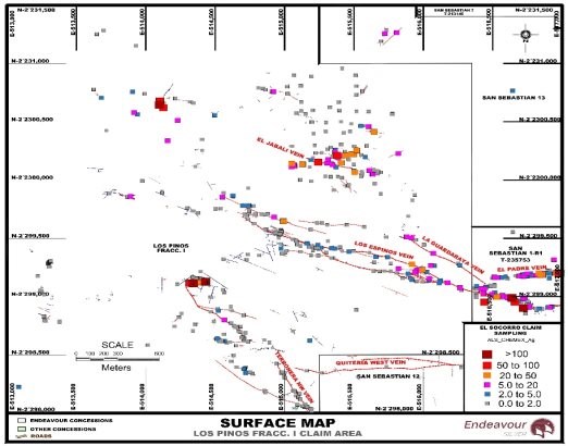
Source: Endeavour Silver, 2017
Coordinate system: WGS 84 / UTM Zone 13Q
Figure 9-1 Silver Results in the Terronera North, Quiteria West, Los Espinos-Guardarraya, and El Jabalí Areas
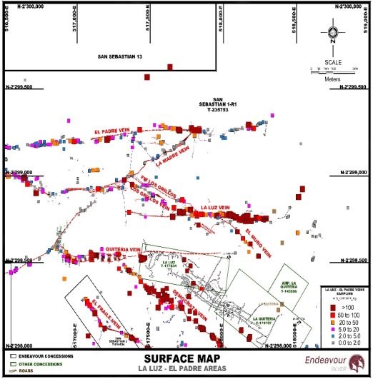
Source: Endeavour Silver, 2017
Coordinate system: WGS 84 / UTM Zone 13Q
Figure 9-2 Silver Results in El Padre, La Madre, La Luz, Quiteria West, Democrata and El Fraile Area
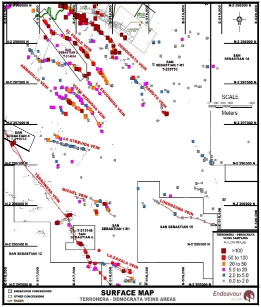
Source: Endeavour Silver, 2017
Coordinate system: WGS 84 / UTM Zone 13Q
Figure 9-3 Silver Results in the Democrata, El Fraile, La Escondida, Vista Hermosa, El Armadillo, La Atrevida, Miguel, Lorenzana, Terronera and Zavala Areas
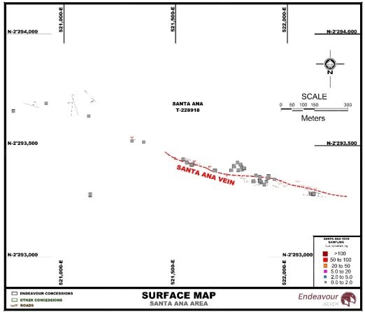
Source: Endeavour Silver, 2017
Coordinate system: WGS 84 / UTM Zone 13Q
Figure 9-4 Silver Results in the Santa Ana Area
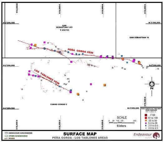
Source: Endeavour Silver, 2017
Coordinate system: WGS 84 / UTM Zone 13Q
Figure 9-5 Silver Results in the Peña Gorda and Los Tablones
9.4 Terronera NW
At the northwest end of the Terronera vein, there are intermittent outcrops for approximately 800 m (Figure and Figure ), which suggests an irregular structure displaced by a fault, both laterally and vertically, with widths varying from 0.3 to 0.7 m. The general trend of the structure is N50°W dipping 70° to the northeast. The structure consists of white quartz, with moderate amounts of iron oxides and traces of manganese oxides. Sampling indicated isolated anomalous gold and silver.
Samples from a three-trench program returned low gold and silver values.
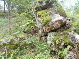
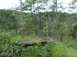
Figure 9-6 Terronera NW Vein Outcrop Photographs Showing Massive, White Quartz with Values of 1.0 g/t Ag
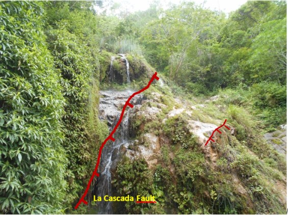
Figure 9-7 Terronera NW Vein Photograph Showing the Vertical Displacement of the Vein by Faulting
9.5 Quiteria West
Exploration activities in the Quiteria West area consisted of detailed mapping to identify drill targets.
In general, the vein consists of white to gray quartz with traces of disseminated sulphides. It has a 1,300 m strike length and variable widths from 0.5 m up to 2.0 m, a preferential east-west trend, and dips at 60° to the south.
Along the structure are located several small mine workings including the Las Arañas, El Zancudo, and La Cacariza mines. These exposures show; medium to low temperature quartz textures. Sampling returned gold values that ranged from 0.005 to 0.044 g/t Au and silver values that ranged from 0.5 to 27 g/t Ag. Although these results are not encouraging, reconnaissance drilling is recommended.
9.6 Los Espinos-La Guardarraya
Geological mapping and sampling were conducted at the northwest to western end of the Los Espinos vein, to verify vein continuity. Reconnaissance mapping was conducted at the east end of the structure, to determine if the vein was associated with the La Luz vein system.
The Los Espinos vein is located north of the Quiteria West vein, inside the Los Pinos Fracc. 1 Endeavour Silver Concession. The vein has approximately 1.1 km of strike length and is a massive, white quartz vein with dendritic manganese and iron oxide zones in fractures (Figure and Figure ).
Two sub-parallel veins with opposite dips were located. The host quartz vein is very fractured with traces of sulphides, and there were abundant quartz float zones.
The general trend is N75°-80°W, dipping at 75° to the southwest. Locally 70° cips to the northeast were observed.
Sampling returned gold values that ranged from 0.005 to 0.118 g/t Au and silver values that ranged from 0.2 to 32.2 g/t Ag. The width of the structure varies from 1 to 20 m. The vein is located along a contact contact between rhyolitic rocks and a volcano-sedimentary sequence.
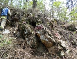
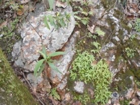
Figure 9-8 Los Espinos Vein Photographs with FeO, MnO and Some Sporadic Oxidized Pyrite
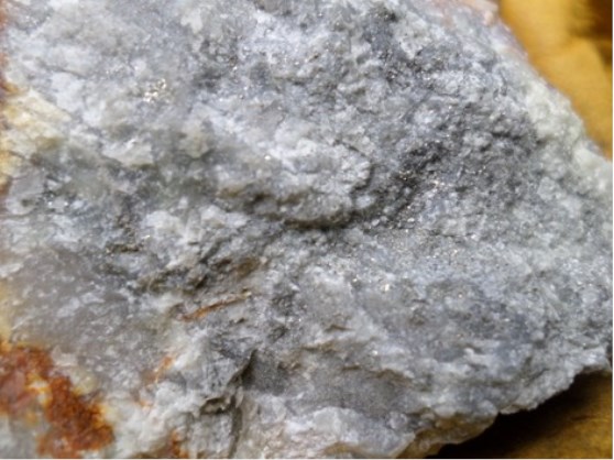
Figure 9-9 Los Espinos Vein Photograph with FeO, MnO and Sporadic Oxidized Pyrite
9.7 El Jabalí
The El Jabalí area is located northeast of the Los Espinos-La Guardarraya veins, within the Los Pinos Fracc. 1 Endeavour Silver Concession(Figure ).
Sampling identified a northwesterly-trending zone of base metal-silver anomalism as shown in Figure and outlined by the contour plots in Figure .
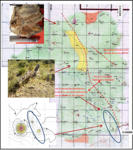
Source: Endeavour Silver (2017)
Coordinate system: WGS 84 / UTM Zone 13Q
Figure 9-10 El Jabalí Surface Map and Photographs Showing the General Zone Trend
Silver Coordinate system: WGS 84 / UTM Zone 13Q
| Lead Coordinate system: WGS 84 / UTM Zone 13Q
|
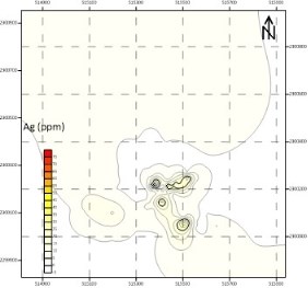
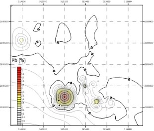
Figure 9-11 Isovalue Diagrams Showing the Trends of the Silver and Lead Anomalies with the Northwest Trend
Zinc Coordinate system: WGS 84 / UTM Zone 13Q
| Copper Coordinate system: WGS 84 / UTM Zone 13Q
|
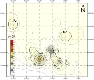
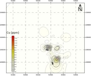
Figure 9-12 Isovalue Diagrams Showing Trends of Zinc and Copper Anomalies with the Northwest Trend
9.8 El Fraile
The El Fraile vein is located in the San Sebastian 2 and San Sebastian 1-R-1 concessions. The structure generally trends SE60°NW, dipping at 65° to the southwest. The approximate strike length of the structure is 1.0 km, and it has variable widths ranging from 0.6 m to 2.5 m.
The structure consists of white to crystalline quartz, that turns partially grayish due to fine sulphide content. It has a moderate manganese content. Figure shows cavities in the vein have been filled by limonite + hematite. The host rock is a sequence of andesites (Kma) and rhyolites (Kmr). Eight trenches have tested the vein. Trench sampling returned gold values that ranged from 0.008 to 2.25 g/t and silver values that ranged from 0.5 to 945 g/t.
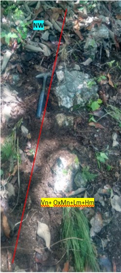
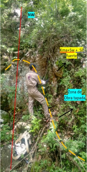
Figure 9-13 El Fraile Vein Photographs Looking Northwest
Figure is taken looking to the northwest at the El Fraile vein. The left image shows white to crystalline quartz (Vn), with open space cavities, weakly developed iron oxides (Lm + Hm), and sporadic and isolated druses filled with manganese oxides (OxMn). The vein is identified by the red line. The right image also looks northwest, the strike of the vein is marked by the red line. The dashed line shows vein fragments. Samples were taken at the footwall of the vein, and included moderate veinlets of white to crystalline quartz, cavities filled with Mn limonites. The mine working were buried by overburden accumulates, andesitic rubble and vein fragments.
9.9 Vista Hermosa
The Vista Hermosa structure is located on the hanging wall of the Terronera vein system, inside the San Sebastian 1-R-1 r Concession. Ithas an inferred strike length of 965 m, a general trend of NW60°SE, and dips from 55° to 70° to the southwest. The vein crops out at its southwest end, where it has a width of up to 3 m.
A secondary parallel structure was located in the area, which consisted of silicified rhyolitic tuff, with abundant veinlets of white to crystalline quartz, considerable hematite filling fractures, sporadic oxidized pyrite, and traces of MnO.
Two historic mine workings were located the first, northwest of the vein, consists of a small adit that is 2.8 m deep. The working, located to the southeast of the vein, consisted of an adit 7.30 m long, 1.30 m wide and 0.80 m high. The adit followed the trend of the vein, Figure .
Five trenches were excavated and sampled. Gold values ranged from 0.005 to 1.72 g/t and silver values ranged from 0.2 to 45.9 g/t.
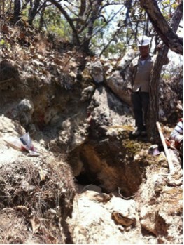
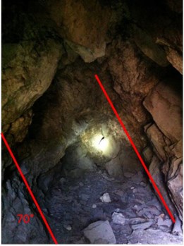
Figure 9-14 Mine Working Over the Vista Hermosa Vein, Photographs with White and Crystalline Quartz, 0.90 m Wide Vein
9.10 La Escondida
The structure identified as La Escondida is located inside the San Sebastian 1-R-1 Concession, hosted at the northwest end in rhyolite (Kmr), and at the southeast end in andesite (Kma) and (Kmr). It is a milky quartz vein, with moderate MnO + limonite filling.
Four mine workings, approximately 2 to 8 m deep, with a general trend of SE60°SW and dipping at 40° to 50° to the southwest, are located over the length of the structure. Figure shows one of the mine workings, the El Ñero Mine.
The excavations indicate that the vein is irregular due to pronounced inflections near faults and/or when it is exposed in creeks. Sub-parallel veins that have irregular widths from 0.15 m to 0.50 m, were observed where the sub-veins join the main structure at depth.
The La Escondida vein has an inferred strike length of about 900 m, and ranges from 0.30 m to 1.0 m in width.
Twelve trenches were excavated and sampled. Gold grades varied from 0.005 to 1.49 g/t and silver grades ranged from 0.2 to 152 g/t.
12 trenches were constructed over the structure in the area. In the area the values of gold vary from 0.005 to 1.49 g/t and silver from 0.2 to 152 g/t.
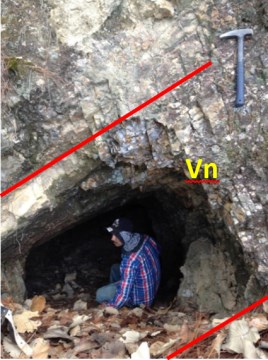
Figure 9-15 El Ñero Mine Photograph 1 m Wide Vein
Figure shows the El Ñero Mine. In the left image the vein is about 1.0 m in width, trending SE70°NW/46° SW, and hosted in andesite (Kma). The mine working is about 8 m in length. The right photograph is of the northwestern portion of the vein, which is about 1.20 m in widthand trends NW50°SE/70°SW.
9.11 El Armadillo
The El Armadillo structure is parallel to the Vista Hermosa vein and is located to the southwest of that vein. The El Armadillo vein consists of an oxidized monomictic breccia/vein, containing rhyolite (Kmr) clasts that may be as large as 3 cm, cemented by white to crystalline quartz. Greyish zones may reflect areas of elevated sulphide content. The structure has been mapped for a distance of 225 m. The average trend is NW70°SE, dipping at 65° to the southwest, with a width that ranges between 0.6 m and 2.4 m, see Figure . The country rock is rhyolite (Kmr),. At the northwest end, the structure is truncated at the contact with the andesitic unit (Kma). Oxidation and argillization were observed.
A total of six trenches were excavated and sampled, primarily at the southeast end of the vein. A historic mine working was located in the area with dimensions of 2 m deep, 0.6 m high and 0.9 m wide.
Gold grades ranged from 0.005 to 0.884 g/t Au and silver grades were from 0.2 to 223 g/t Ag.
Figure 9-16 El Armadillo Vein Photographs with Sulphides Inside the Vein
9.12 La Atrevida
The La Atrevida vein is located at the north end of the Terronera vein and south of Quiteria, within the San Sebastian 1-R-1 Concession. The structure consists of crystalline quartz that displays saccaroidal textures, brecciated zones, moderate iron oxide content ( limonite and hematite), and selective argillization(Figure ). The general trend is S75°-80°E, dipping at 75° to the southwest. The approximate strike length of the vein is 550 m, and it has a variable width from 0.30 m to 3.0 m. Two vein splays were noted, one in the footwall, and the second in the hanging wall of the main vein. The host rock is rhyolite (Kmr). To the northwest the vein is located on the andesite contact.
Six trenches were excavated and sampled. Gold grades ranged from 0.005 to 0.715 g/t Au and silver values were from 0.2 to 30.9 g/t Ag.
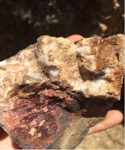
Figure 9-17 Quartz Veinlet Photographs 10 cm Wide Veinlet, with Moderate FeO, Weak Selective Argillization, Small Rhyolite Clasts
9.13 Santana
The Santana structure crops out in the vicinity of the road to the town of Santana, and may represent the southeastern end of the Terronera vein. The area consists of a wide zone of well-developed iron oxide alteration (limonite, hematite, and possible jarosite), and moderate to strong argillization. Quartz within the structure, is crystalline with minor white quartz, which has been re-worked and fractured (Figure to Figure ). Some portions of the vein display silica replacement. The vein has a general trend of N70°W, dipping at 80° to the northeast. It has been outlined over a 600 m length, and the alteration zone displays widths from 0.3 to 1.0 m.
In creek exposures, the vein was strongly-silicified structure consisting of crystalline quartz, minor quartz that had moderate iron oxides associated, and finely-disseminated pyrite.
To the northwest, the structure does not crop out; however, there are alteration zones featuring iron oxides and argillization, and minor micro-veinlets in andesites.
At the southeastern end of the vein, intermittent zones were observed that displayed strong iron oxide alteration (limonite, hematite and possible jarosite), and moderate to strong argillization. Within the altered zone, a system of quartz (crystalline and minor white) t veinlets was observed, together with strongly silicified zones and traces of pyrite. The host rock is andesite.
In the outcropping zones the structure may be as wide as 1 width. Otherwise, the areas of interest consist of alteration haloes that display iron oxides, argillization, silicification and veinlets. The trend of the alteration is approximately NW70°SE.
The gold and silver values in the collected rock samples are generally low (0.005 to 0.019 g/t Au and 0.2 to 1.8 g/t Ag). However, the area has remaining potential because of the continuous nature of the moderate to strong argillic and iron oxide alteration, which may reflect a buried structure at depth.
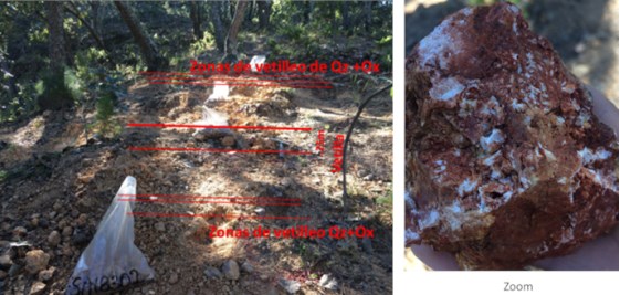
Figure 9-18 Quartz Vein Photographs
Figure Left: crystalline quartz vein with abundant iron oxides (hematite>limonite), containing minor fragments of silicified rock, with veinlets of quartz, and moderate argillization.
Error! Reference source not found.Figure Right: an example of a quartz veinlet of displayingiron oxidation and strong silicification.
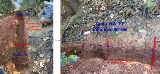
Figure 9-19 Trench Photographs
Trench photographs, Figure , show quartz-crystalline vein with abundant iron oxides (hematite>limonite) that contain minor fragments of silicified rock, with veinlets of quartz, moderate argillization, and intense fracturing.
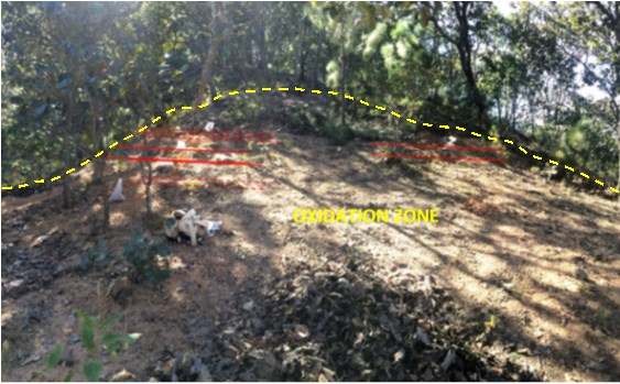
Figure 9-20 Panoramic View of the Santana Vein Trace with Evidence of Quartz Veinlets and FeO
9.14 Peña Gorda
The vein identified as Peña Gorda is located south of the Real Alto area, at the southern part of the San Sebastian 1-R-1 Concession and the Cerro Gordo 2 r Concession. The structure is oriented east-west, with a general trend of N80°W, dipping at 85° to the southwest. The vein has been traced for around 1.4 km, and may reach as much as 10 m in width. The structure consisted of white to crystalline quartz, with iron and manganeseoxides, and pyrite traces (partially oxidized) in boxwork zones. No other sulphides were visible (Figure ).
In general, the host rock is of rhyolitic composition, consisting of rhyolitic agglomerate with traces of iron oxides.
The surface sampling program showed anomalous gold values of, associated with areas that displayed moderate oxidation in fractures. Sample results ranged from 0.005 to 0.512 g/t Au and 0.2 to 37.2 g/t Ag.
Although the sample results are not encouraging, additional work is recommended based on the vein proximity to the El Tajo, Los Negros and Real veins.
Peña Gorda Vein Peña Gorda Vein Outcrops
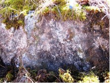
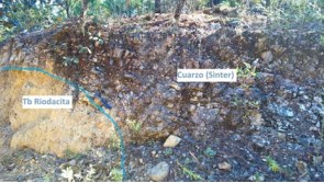
Figure 9-21 Peña Gorda Vein Photographs with Outcrops for Approximately 1.4 km
9.15 San Joaquin
The San Jaoquin vein is oriented east-west. It consists of a white, massive quartz body of (), which can display a weakly saccharoidal texture, cavities and bladed textures. The structure has a general trend of N65°W, dipping at 80° to the southwest, and displaying a slight inflection towards the west in the northwestern segment(Figure ).
The width of the structure varies from 0.35 m in the southeast up to 4 m in the central area. the behavior in the west area is as an outcrop of rhyolite with a stockwork of quartz, gradually decreasing until it practically disappears inside the mapped area. The vein is hosted in a rhyolitic unit, which is practically fresh and hydrothermally unaltered, except for development of weak and sporadic veinlets in the hanging wall of the main structure.
Rock samples show values that ranged from 0.006 to 0.324 g/t Au and 0.2 to 28.8 g/t Ag.
Figure 9-22 Outcrop of the Los Tablones Vein (Quartz Vein)
10.1 2011 to 2016 Drilling
The drill programs conducted by Endeavour Silver between 2011 and 2018 are summarized in this Updated Technical Report section.
10.2 2011 Drilling Program
In 2011, Endeavour Silver commenced a surface diamond drilling program on prospective targets within the Terronera Project. Exploration drilling focused on two main areas: 1) The Real el Alto area, exploring the Animas-Los Negros, El Tajo and Real Veins; and 2) The Central area, exploring the extension of the Quiteria Vein, west of the La Quiteria Mine.
By mid-December 2011, Endeavour Silver had completed 7,688.25m of drilling in 36 surface diamond drill holes on the Terronera Project. A total of 2,980 diamond drill core samples were analyzed.
Drilling identified the Animas-Los Negros Vein in the Real el Alto area (Figure 10-1), which was found to be one vein, offset by faulting. The vein is principally hosted in rhyolite and is comprised of quartz with abundant manganese oxides (pyrolusite), minor pyrite and traces of disseminated dark grey and blue sulphides. Highlights include:
• 132 g/t Ag and 1.02 g/t Au over a 3.2m true width in hole LN07-1
• 144 g/t Ag and 1.21 g/t Au over a 3.6m true width in hole LN08-1
• 258 g/t Ag and 0.61 g/t Au over a 4.5m true width was returned for hole LN09-1.
The 2011 drill program also outlined new Mineral Resources on the El Tajo Vein area. El Tajo is believed to be either a brecciated quartz +/- calcite vein or a stockwork zone with weak to moderate veinlets and disseminations of fine pyrite and traces of galena and possible silver sulphides (possibly argentite). Drilling highlights in the El Tajo Vein include:
• 107 g/t Ag and 0.10 g/t Au over 1.6m true width within hole TA03-1; and
• 169 g/t Ag and 0.63 g/t Au over a 3.0m true width in hole TA04-1.
New Mineral Resources were also outlined on the Real Vein, which is located to the northeast of the Animas-Los Negros and El Tajo Veins. The most significant intercept for the Real Vein was in hole RE04-1 which returned:
• 320 g/t Ag and 0.74 g/t Au over a true width of 2.6m.
Drill holes were also advanced on the La Escurana and La Luz Veins but did not return significant gold or silver mineralization.
10.3 2012 Drilling Program
In 2012, Endeavour Silver continued its diamond drilling program on the Terronera Property to expand Mineral Resources defined in the 2011 drill program. Exploration drilling focused on two main areas: 1) The Real el Alto area, exploring the Animas-Los Negros and Real Veins; and 2) The Central area, exploring the extension of the Quiteria Vein, west of the La Quiteria Mine, and the Terronera Vein. Endeavour Silver completed 13,237.10m of drilling in 32 diamond drill holes on the Terronera Property. A total of 3,118 samples were collected for analysis.
Drill holes advanced on the Animas-Los Negros Vein were successful in intercepting the mineralized zone at depth. These drill holes also passed through the La Escurana Vein in the upper part of each drill hole. The Escurana Vein is located in the southernmost part of the Real el Alto area. Two holes were advanced on the Real Vein but did not return significant intersections. Only one hole was drilled on the Quiteria Vein in the La Luz area. The only intersection of note was:
• 15 g/t Ag and 0.02 g/t Au over 5.2m in hole QT05-2.
The 2012 drill program discovered a new, high grade, silver-gold mineralized zone in the Terronera Vein. The Terronera Vein mainly consists of brecciated to massive quartz +/- calcite, locally banded and sugary-textured. Sulphide content is typically <1% and predominately fine-grained pyrite.
Drilling highlights in the Terronera Vein include:
• 1,489 g/t Ag and 0.85 g/t Au over a 5.66m true width in hole TR02-1; and
• 500 g/t Ag and 1.15 g/t Au over an 11.48m true width in hole TR12-1.
• Hole TR09-1 yielded:
o 650 g/t Ag and 1.17 g/t Au over a 5.50m true width; and
o 519 g/t Ag and 0.47 g/t Au over a 9.02m true width.
10.4 2013 Drilling Program
In 2013, Endeavour Silver continued its diamond drilling program on the Terronera Property to expand Mineral Resources defined in the 2012 drill program. Drilling in 2013 focused on the Terronera Vein area.
Endeavour Silver completed 8,573.5m of drilling in 30 drill holes in 2013. The 2013 program was successful in expanding and connecting the two high grade silver-gold mineralized zones, the Central Area and the El Hundido areas, in the Terronera Vein.
Drilling highlights from the Terronera Vein include:
• 122 g/t Ag and 2.00 g/t Au over a 5.90m true width in hole TR02-5
• 507 g/t Ag and 1.36 g/t Au over a 6.66m true width in hole TR03-1
• 915 g/t Ag and 2.33 g/t Au over a 2.47m true width in hole TR03-5
o Including 5,580 g/t Ag and 15.85 g/t Au over a 0.27m true width
• 646 g/t Ag and 1.11 g/t Au over a 5.03 m true width in hole TR07.5-1
o Including 1,650 g/t Ag and 1.82 g/t Au over a 1.04m true width; and
• 583 g/t Ag and 0.79 g/t Au over an 8.41m true width in hole TR08.5-1
o Including 4,420 g/t Ag and 2.46 g/t Au over a 0.47m true width.
10.5 2014 Drilling program
In 2014, Endeavour Silver continued its drilling program on the Terronera Property. Endeavour Silver’s objective for the drilling campaign was to continue defining the mineralized body and to expand upon Mineral Resources identified in the 2012-2013 drill programs. Endeavour Silver was successful in meeting its objectives for the 2014 drilling program.
As at September 2014, Endeavour Silver completed a total of 8,204.20m in 27 surface diamond drill holes at the Terronera Project. A total of 2,470 samples were collected and submitted for assays.
The 2014 exploration drilling program was conducted with the objective to continue defining the high grade silver-gold mineralized body between sections TR-4S through TR-41, primarily on the Central Area (between sections TR-07 through TR-23).
Drilling highlights for Terronera Vein included:
• 499 g/t Ag & 1.4 g/t Au over 2.6m true width in hole TR07-3
o Including 1,660 g/t Ag & 1.3 g/t Au over 0.2m true width
• 345 g/t Ag & 0.8 g/t Au over 6.3m true width in hole TR14-3
o Including 1,440 g/t Ag & 1.0 g/t Au over 0.5m true width
• 301 g/t Ag & 0.7 g/t Au over 6.7m true width in hole TR15-2
o Including 1,250 g/t Ag & 1.4 g/t Au over 0.4m true width
• 788 g/t Ag & 0.8 g/t Au over 3.8m true width in hole TR17-2
o Including 3,620 g/t Ag & 2.0 g/t Au over 0.7m true width
• 106 g/t Ag & 5.5 g/t Au over 3.2m true width in hole TR20-1
• 272 g/t Ag & 8.5 g/t Au over 3.0m true width in hole TR20-2
• 105 g/t Ag & 5.0 g/t Au over 2.6m true width in hole TR21-1
• 121 g/t Ag & 3.3 g/t Au over 16.0m true width in hole TR23-1.
Also, significant results were returned for Hanging Wall Terronera Vein 1:
• 101 g/t Ag & 4.3 g/t Au over 8.2m true width in hole TR21-1
• 114 g/t Ag & 3.9 g/t Au over 4.1m true width in hole TR22-2
• 107 g/t Ag & 1.9 g/t Au over 7.9m true width in hole TR23-1.
10.6 2015 Drilling Program
In 2015, Endeavour Silver continued its drilling program on the Terronera Property. Endeavour Silver’s objective for the drilling campaign was to continue defining the mineralized body and to expand upon Mineral Resources identified in the 2012-2014 drill programs. Endeavour Silver was successful in meeting its objectives for the 2015 drilling program.
Endeavour Silver completed a total of 6,133m in 27 surface diamond drill holes at the Terronera Project in 2015. A total of 3,756 samples were collected and submitted for assays.
Drilling highlights for the Terronera Vein include:
• 1,371 g/t Ag and 1.10 g/t Au (1,448 g/t AgEq) over 6.6m true width
o Including 5,420 g/t Ag
• 5.12 g/t Au (5,778 g/t ageq) over 0.3m true width in hole TR 10-4
• 508 g/t Ag and 3.25 g/t Au (735 g/t ageq) over 8.2m true width
o Including 6,600 g/t Ag and 22.10 g/t Au (8,147 g/t Ag Eq) over 0.23m true width in hole TR18-5.
10.7 2016 Drilling Program
In 2016, Endeavour Silver continued its drilling program on the Terronera Property in 2016. The aim of the 2016 drilling program was to continue infill drilling within the Terronera Vein system and conducted exploration drilling on the La Luz Vein, located about 2,200m northeast of the Terronera Vein.
Endeavour Silver completed a total of 5,670m in 19 surface diamond drill holes at the Terronera Project in 2016. A total of 1,805 samples were collected and submitted for assays.
Drilling highlights for Terronera Vein include:
• 717 g/t Ag and 2.94 g/t Au (923 g/t ageq) over 6.56m true width,
- Including 4,860 g/t Ag and 2.99 g/t Au (5,069 g/t ageq) over 0.39m true width in hole TR10.5-1; and
• 226 g/t Ag and 5.0 g/t Au (576 g/t ageq) over 6.74m true width,
- Including 527 g/t Ag and 169 g/t Au (1,710 g/t ageq) over 0.7m true width in hole TR09-06.
Drilling on the La Luz Vein outlined a west plunging mineralized zone over 300m by 250m deep starting approximately 100m below surface and still open to surface and to depth. Highlights include:
• 408 g/t Ag and 58.6 g/t Au (4,512 g/t ageq) over 1.14m true width,
- Including 1,365 g/t Ag and 238.0 g/t Au (18,025 g/t ageq) over 0.9m true width in hole LL-02.
10.8 2017 Drilling Program
In 2017, Endeavour Silver drilling programs focused on the definition of potential economical mineralization in several structures located in the northwest and east-west systems of the Terronera Project.
The drilling program included a total of 12,252m drilled in 47 surface diamond drill holes, mainly conducted at La Luz. Eight other structures were tested (El Muro, Los Espinos, Los Reyes, El Fraile, Vista Hermosa, La Escondida, La Atrevida and Quiteria West). The 2017 drilling program included 2,308 samples.
Surface drilling conducted during 2017 is summarized in
Table 10-1 and shown on the map in Figure 10-1.
Table 10-1 Terronera Project Surface Drilling in 2017
Project Area | No. of Holes | Total Length (m) | No. of Samples Taken |
La Luz | 25 | 5,760 | 1031 |
El Muro | 1 | 226 | 52 |
Los Espinos | 2 | 436 | 169 |
Los Reyes | 6 | 1,957 | 646 |
El Fraile | 7 | 1,749 | 164 |
Vista Hermosa | 1 | 642 | 78 |
La Escondida | 1 | 360 | 37 |
La Atrevida | 1 | 340 | 11 |
Quiteria West | 3 | 782 | 120 |
Total | 47 | 12,252 | 2,308 |
Note: Completed drill hole are shown in black
Source: Endeavour Silver (2017)
Coordinate system: WGS 84 / UTM Zone 13Q
Figure 10-1 Terronera Surface Map Showing 2017 Completed Drill Holes
Surface diamond drilling was conducted by Energold de Mexico, S.A. de C.V. (Energold Mexico) a wholly owned subsidiary of the Energold Drilling Corp. (Energold) based in Vancouver, British Columbia, Canada, using two man-portable drill rigs. Energold Mexico and Energold do not hold any interest in Endeavour Silver and are independent of the company.
Except for La Luz, the results of the drilling campaigns in the eight other structures were not significant. However, there are still possibilities to locate mineralization at the southeast part of Terronera, deep Quiteria, northwest part of Los Espinos, the new discoveries of Peña Gorda-Los Tablones and over structures at the Real Alto area.
In 2017 follow-up surface diamond drilling resumed on the La Luz Vein area, totalling 25 drill holes with 5,760 m drilled (Table 10-2).
The ultimate objective of the La Luz drilling program conducted in 2017 was to add Mineral Resources to the Terronera Project by defining the high-grade silver-gold mineralized body discovered in 2016, which was expanded to over 600m long by 250m deep starting approximately 100m below surface and still open to surface and to depth. The La Luz Vein mainly consists of quartz (banded, massive and brecciated), white and amethyst quartz, gray silica, traces of chlorite, greenish clays, micro-veinlets of calcite, selective argillization, strong silicification, FeO in fractures, weak to moderate disseminated pyrite and sulphides of Ag in bands and disseminated. The host rock is a volcano-sedimentary sequence from the lower Cretaceous.
Table 10-2 2017 Drill Hole Summary for the La Luz Surface Drilling Program
Hole No. | Azimuth | Dip | Core Diameter | Total Depth (m) | Start Date | Finish Date |
LL-17 | 355 º | -45 º | HTW | 169.25 | 16/01/2017 | 20/01/2017 |
LL-18 | 356 º | ˗56 º | HTW | 254.65 | 21/01/2017 | 26/01/2017 |
LL-19 | 356 º | -61 º | HTW/NTW | 277.55 | 26/01/2017 | 31/01/2017 |
LL-20 | 333 º | -48 º | HTW | 205.85 | 01/02/2017 | 04/02/2017 |
LL-21 | 0 º | -45 º | HTW | 212.15 | 05/02/2017 | 10/02/2017 |
LL-22 | 0 º | -53 º | HQ/NQ | 326.35 | 10/02/2017 | 18/02/2017 |
LL-23 | 19 º | 45 º | HQ | 217.55 | 25/02/2017 | 02/03/2017 |
LL-24 | 165 º | -69 º | HQ | 197.00 | 03/03/2017 | 08/03/2017 |
LL-25 | 151 º | -53 º | HTW | 311.10 | 08/03/2017 | 15/03/2017 |
LL-26 | 170 º | -64 º | HTW/NTW | 340.05 | 16/03/2017 | 30/03/2017 |
LL-27 | 158 º | -75 º | HQ | 305.00 | 30/03/2017 | 06/04/2017 |
LL-28 | 208 º | -49 º | HTW | 216.55 | 08/04/2017 | 11/04/2017 |
LL-29 | 209 º | -56 º | HQ/NTW | 323.30 | 21/05/2017 | 27/05/2017 |
LL-30 | 144 º | -61 º | HQ/NTW | 312.10 | 27/05/2017 | 02/06/2017 |
LL-31 | 229 º | -62 º | HQ | 374.60 | 03/06/2017 | 09/06/2017 |
LL-32 | 209 º | -46 º | HQ/NTW | 250.10 | 09/06/2017 | 15/06/2017 |
Hole No. | Azimuth | Dip | Core Diameter | Total Depth (m) | Start Date | Finish Date |
LL-33 | 180 º | -45 º | HQ | 118.95 | 16/06/2017 | 18/06/2017 |
LL-34 | 230 º | -45 º | HTW | 163.15 | 19/06/2017 | 22/06/2017 |
LL-35 | 206 º | -61 º | HQ | 130.30 | 23/06/2017 | 25/06/2017 |
LL-36 | 127 º | -45 º | HQ | 91.50 | 26/06/2017 | 28/06/2017 |
LL-37 | 177 º | -54 º | HQ | 111.30 | 28/06/2017 | 30/06/2017 |
LL-38 | 127 º | -45 º | HQ | 176.00 | 01/07/2017 | 04/07/2017 |
LL-39 | 137 º | -62 º | HQ | 193.65 | 05/07/2017 | 08/07/2017 |
LL-40 | 120 º | -52 º | HQ | 227.20 | 09/07/2017 | 15/07/2017 |
LL-41 | 332 º | -57 º | HQ | 254.65 | 16/07/2017 | 22/07/2017 |
Total (25 drill holes) | 5,759.85 |
|
| |||
Drilling highlights for La Luz Vein include:
• 245 g/t Ag and 23.1 g/t Au (1,980 g/t AgEq) over 1.4m true width in hole LL-17
• 25 g/t Ag and 14.9 g/t Au (1,146 g/t AgEq) over 1.8m true width in hole LL-18
• 63 g/t Ag and 57.0 g/t Au (4,339 g/t AgEq) over 2.2m true width in hole LL-21
- including 340 g/t Ag and 320.0 g/t Au over 0.3m true width
• 45 g/t Ag and 16.2 g/t Au (1,262 g/t AgEq) over 1.7m true width in hole LL-23
• 384 g/t Ag and 20.3 g/t Au over 1.1m true width in hole LL-35
- including 2,600 g/t Ag and 123.5 g/t Au over 0.12m true width
• 38 g/t Ag and 16.5 g/t Au (1,273 g/t AgEq) over 1.2m true width in hole LL-36.
Also, significant results were returned for the La Luz HW Vein including:
• 25 g/t Ag and 20.9 g/t Au (1,589 g/t AgEq) over 1.3m true width in hole LL-23
• 12 g/t Ag and 7.6 g/t Au (580 g/t AgEq) over 1.2m true width in hole LL-39.
Drilling results of La Luz Vein are summarized in Table 10-3 and the La Luz Vein intercepts are shown on the longitudinal projection in Figure 10-2.
Table 10-3 Surface Drill Hole Significant Assay Summary for Mineral Intercepts in the La Luz Vein Area
Drill Hole No. | Structure | Mineralized Interval | Assay Results | ||||
From (m) | To (m) | Core Length (m) | True Width (m) | Ag (g/t) | Au (g/t) | ||
LL-17 | La Luz Vein | 124.15 | 127.85 | 3.7 | 2.3 | 164 | 14.5 |
La Luz Composite | 124.55 | 126.85 | 2.3 | 1.4 | 245 | 23.1 | |
Including | 124.55 | 125.40 | 0.9 | 0.5 | 212 | 47.5 | |
LL-18 | La Luz Vein | 174.00 | 178.10 | 4.1 | 1.8 | 25 | 14.9 |
Including | 177.60 | 178.10 | 0.5 | 0.2 | 77 | 48.5 | |
LL-20 | La Luz Vein | 168.00 | 172.30 | 4.3 | 2.1 | 39 | 4.8 |
La Luz Composite | 169.15 | 172.30 | 3.2 | 1.5 | 40 | 6.4 | |
Including | 171.75 | 172.30 | 0.6 | 0.3 | 21 | 12.4 | |
LL-21 | La Luz Vein | 172.70 | 174.15 | 1.5 | 0.9 | 137 | 127.5 |
La Luz Composite | 173.10 | 176.75 | 3.7 | 2.2 | 63 | 57.0 | |
Including | 173.60 | 174.15 | 0.6 | 0.3 | 340 | 320.0 | |
LL-23 | La Luz Vein | 144.75 | 147.90 | 3.2 | 2.0 | 39 | 13.9 |
La Luz Composite | 145.20 | 147.90 | 2.7 | 1.7 | 45 | 16.2 | |
Including | 147.05 | 147.40 | 0.3 | 0.2 | 171 | 45.2 | |
Hw La Luz Vein | 154.50 | 156.20 | 1.7 | 1.0 | 31 | 26.2 | |
Hw La Luz Composite | 154.50 | 156.70 | 2.2 | 1.3 | 25 | 20.9 | |
Including | 154.50 | 155.05 | 0.6 | 0.3 | 44 | 31.6 | |
LL-25 | La Luz Vein | 215.90 | 216.65 | 0.8 | 0.5 | 1114 | 0.6 |
La Luz Composite | 214.65 | 216.65 | 2.0 | 1.4 | 419 | 0.2 | |
Including | 216.20 | 216.65 | 0.5 | 0.3 | 1830 | 1.1 | |
LL-27 | La Luz Vein | 173.35 | 175.60 | 2.3 | 1.2 | 71 | 2.0 |
Including | 173.35 | 174.30 | 1.0 | 0.5 | 128 | 4.7 | |
LL-32 | La Luz Vein | 196.30 | 197.85 | 1.5 | 1.1 | 91 | 2.7 |
Including | 197.00 | 197.85 | 0.8 | 0.6 | 95 | 4.7 | |
Drill Hole No. | Structure | Mineralized Interval | Assay Results | ||||
From (m) | To (m) | Core Length (m) | True Width (m) | Ag (g/t) | Au (g/t) | ||
LL-35 | La Luz Vein | 106.65 | 107.05 | 0.4 | 0.2 | 1699 | 90.5 |
La Luz Composite | 105.20 | 107.05 | 1.8 | 1.1 | 384 | 20.3 | |
Including | 106.65 | 106.85 | 0.2 | 0.1 | 2600 | 123.5 | |
LL-36 | La Luz Vein | 57.40 | 58.15 | 0.8 | 0.6 | 57 | 2.5 |
La Luz Composite | 57.40 | 58.75 | 1.4 | 1.2 | 38 | 16.5 | |
Including | 58.15 | 58.75 | 0.6 | 0.5 | 14 | 34.0 | |
LL-39 | Hw La Luz Vein | 146.05 | 146.40 | 0.3 | 0.2 | 25 | 26.9 |
Hw La Luz Composite | 146.05 | 148.45 | 2.4 | 1.2 | 12 | 7.6 | |
Including | 146.05 | 146.40 | 0.3 | 0.2 | 25 | 26.9 | |
La Luz Vein | 162.05 | 163.15 | 1.1 | 0.5 | 6 | 3.2 | |
La Luz Composite | 161.80 | 164.00 | 2.2 | 1.1 | 4 | 1.6 | |
Including | 162.05 | 162.35 | 0.3 | 0.1 | 12 | 8.4 | |
Source: www.endeavoursilver.com
Coordinate system: WGS 84 / UTM Zone 13Q
Figure 10-2 Drill Intersections – La Luz Vein Longitudinal Projection
10.9 2018 Drilling Program
In 2018, Endeavour Silver resumed its drilling program over the Terronera Vein. In addition, at the end of the year, surface diamond drilling was conducted with associated geomechanical and hydrogeological support at the La Luz Vein area.
10.10 Terronera
In 2018, Endeavour Silver conducted an infill surface drilling program over the Terronera Vein, with the objective of filling gaps to upgrade Inferred Mineral Resources to Indicated Mineral Resources and to expand the Inferred Mineral Resources at depth. Mineralization in the Terronera Vein has been intersected over 1,400m long by 500m deep, and it remains open at depth.
The 2018 drilling program included a total of 18,774m drilled in 39 surface diamond drill holes (Figure ), including 3,007 samples collected and submitted for analysis (Table 10-4). The information of these holes is summarized in
Table 10-5.
Table 10-4 Terronera Surface Drilling in 2018
Project Area | Number of Holes | Total Length (m) | Number of Samples Taken |
Terronera | 39 | 18,774 | 3,007 |
Total | 39 | 18,774 | 3,007 |
Table 10-5 2018 Drill Hole Summary for the Terronera Surface Drilling Program
Drill Hole No. | Azimuth | Dip | Core Diameter | Total Depth (m) | Start | Finish |
TR7S-1 | 224 º | -65 º | HQ | 766.15 | 17/03/2018 | 10/04/2018 |
TR11-4 | 229 º | -63 º | HQ | 632.35 | 25/03/2018 | 11/04/2018 |
TR11-5 | 226 º | -59 º | HQ | 608.25 | 11/04/2018 | 26/04/2018 |
TR10-5 | 229 º | -57 º | HQ | 522.65 | 29/04/2018 | 11/05/2018 |
TR10-6 | 229 º | -64 º | HQ | 577.50 | 11/05/2018 | 23/05/2018 |
TR14-8 | 233 º | -73 º | HQ | 406.65 | 23/04/2018 | 02/05/2018 |
TR15-7 | 263 º | -65 º | HQ | 391.30 | 02/05/2018 | 10/05/2018 |
TR13-6 | 197 º | -74 º | HQ | 437.80 | 10/05/2018 | 19/05/2018 |
TR08-6 | 226 º | -66 º | HQ/NQ | 391.90 | 25/04/2018 | 04/05/2018 |
TR07-4 | 207 º | -66 º | HQ/NQ | 395.00 | 05/05/2018 | 15/05/2018 |
TR5S-2 | 249 º | -55 º | HQ/NQ | 570.50 | 01/05/2018 / | 14/05/2018 / |
TR7S-2 | 225 º | -46 º | HQ | 498.50 | 31/05/2018 | 14/06/2018 |
TR10-7 | 229 º | -68 º | HQ | 649.35 | 23/05/2018 | 06/06/2018 |
TR09-7 | 221 º | -66 º | HQ | 609.55 | 06/06/2018 | 19/06/2018 |
TR13-7 | 208 º | -78 º | HQ | 489.00 | 19/05/2018 | 31/05/2018 |
TR12-7 | 199 º | -80 º | HQ | 452.35 | 01/06/2018 | 10/06/2018 |
Drill Hole No. | Azimuth | Dip | Core Diameter | Total Depth (m) | Start | Finish |
TR17-6 | 241 º | -55 º | HQ | 401.35 | 10/06/2018 | 19/06/2018 |
TR06-5 | 189 º | -62 º | HQ/NQ | 405.65 | 16/05/2018 | 29/05/2018 |
TR06-6 | 185 º | -67 º | HQ/NQ | 410.20 | 30/05/2018 | 10/06/2018 |
TR09-8 | 244 º | -68 º | HQ/NQ | 394.95 | 11/06/2018 | 20/06/2018 |
TR2S-4 | 239 º | -65 º | HQ | 533.00 | 16/06/2018 | 07/07/2018 |
TR11-7 | 204 º | -69 º | HQ | 351.90 | 11/07/2018 | 21/07/2018 |
TR12-8 | 213 º | -58 º | HQ | 571.35 | 20/06/2018 | 04/07/2018 |
TR12-9 | 214 º | -62 º | HQ | 629.85 | 05/07/2018 | 19/07/2018 |
TR17-7 | 241 º | -61 º | HQ | 435.65 | 19/06/2018 | 29/06/2018 |
TR18-7 | 254 º | -60 º | HQ | 434.10 | 29/06/2018 | 10/07/2018 |
TR16-10 | 223 º | -61 º | HQ | 432.35 | 11/07/2018 | 21/07/2018 |
TR09-9 | 245 º | -73 º | HQ/NQ | 434.60 | 21/06/2018 | 30/06/2018 |
TR01-4 | 204 º | -66 º | HQ/NQ | 353.80 | 04/07/2018 | 14/07/2018 |
TR00-3 | 183 º | -65 º | HQ/NQ | 419.35 | 15/07/2018 | 27/07/2018 |
TR19-7 | 210 º | -55 º | HQ | 375.85 | 22/07/2018 | 31/07/2018 |
TR11-8 | 186 º | -73 º | HQ | 423.00 | 21/07/2018 | 02/08/2018 |
TR13-8 | 226 º | -59 º | HQ | 610.75 | 19/07/2018 | 04/08/2018 |
TR01-5 | 213 º | -70 º | HQ/NQ | 390.40 | 28/07/2018 | 07/08/2018 |
TR19-8 | 207 º | -63 º | HQ | 411.15 | 31/07/2018 | 10/08/2018 |
TR10-8 | 166 º | -69 º | HQ | 427.00 | 02/08/2018 | 12/08/2018 |
TR13-9 | 224 º | -63 º | HQ | 658.10 | 04/08/2018 | 18/08/2018 |
TR19-9 | 207 º | -68 º | HQ | 463.05 | 10/08/2018 | 21/08/2018 |
TR04-6 | 227 º | -78 º | HQ | 407.45 | 10/08/2018 | 26/08/2018 |
Total (39 drill holes) | 18,773.65 |
|
| |||
Surface diamond drilling conducted by Energold de Mexico, S.A. de C.V. (Energold Mexico) and Layne de Mexico, S.A. de C.V. (Layne).
Energold de Mexico, S.A. de C.V. (Energold Mexico), a wholly owned subsidiary of the Energold Drilling Corp. (Energold) based in Vancouver, British Columbia, Canada, used two drill rigs (one man-portable drill rig). Energold Mexico and Energold do no hold any interest in Endeavour Silver and are independent of the company.
Layne de Mexico, S.A. de C.V. (Layne), a wholly owned subsidiary of the USA-based Layne Christensen Company (Layne Christensen), used two drill rigs. Neither Layne nor Layne Christensen held an interest in Endeavour Silver and both are independent of the Company.

Note: Completed drill hole are shown in black
Source: Endeavour Silver (2018)
Coordinate system: WGS 84 / UTM Zone 13Q
Figure 10-3 Terronera Surface Map Showing Completed 2018 Drill Holes
Drilling at Terronera fulfilled the objective by intercepting high silver and gold grades and proving continuity of the mineralization along strike and to depth.
Drilling highlights for the Terronera Vein include:
• 782 g/t Ag and 0.9 g/t Au (847 g/t AgEq) over 3.3m true width in hole TR10-8, including 9,810 g/t Ag and 8.75 g/t Au over 0.12m true width
• 618 g/t Ag and 3.2 g/t Au (861 g/t AgEq) over 21.2m true width in hole TR11-4, including 4,090 g/t Ag and 4.9 g/t Au over 0.2m true width
• 507 g/t Ag and 2.6 g/t Au (699 g/t AgEq) over 6.0m true width in hole TR11-5, including 3,370 g/t Ag and 5.4 g/t Au over 0.4m true width
• 783 g/t Ag and 1.2 g/t Au (874 g/t AgEq) over 5.3m true width in hole TR11-7, including 3,880 g/t Ag and 2.6 g/t Au over 0.3m true width
• 524 g/t Ag and 0.7 g/t Au (575 g/t AgEq) over 4.2m true width in hole TR11-8
• 197 g/t Ag; and 2.4 g/t Au (378 g/t AgEq) over 9.8m true width in hole TR12-8, including 3,420 g/t Ag and 6.6 g/t Au over 0.2m true width
• 129 g/t Ag and 4.8 g/t Au (488 g/t AgEq) over 4.4m true width in hole TR13-7
• 185 g/t Ag and 7.15 g/t Au (721 g/t AgEq) over 5.6m true width in hole TR13-9
• 129 g/t Ag and 2.8 g/t Au (340 g/t AgEq) over 7.2m true width in hole TR14-8.
Also significant results returned for the Terronera FW Vein:
• 1,297 g/t Ag and 0.9 g/t Au over 6.1m true width in hole TR11-8, including 6,660 g/t Ag and 1.8 g/t Au over 0.5m true width
• 169 g/t Ag and 4.75 g/t Au over 7.7m true width in hole TR12-7.
Drilling results of Terronera Vein are summarized in Table 10-6 and the Terronera Vein intercepts are shown on the longitudinal projection in Figure 10-4.
Table 10-6 2018 Drill Hole Assay Summary for the Terronera Surface Drilling Program
Drill Hole No. | Structure | Mineralized Interval | Assay Results | ||||
From (m) | To (m) | Core Length (m) | True Width (m) | Ag (g/t) | Au (g/t) | ||
TR2S-4 | Terronera | 451.75 | 453.40 | 1.6 | 0.8 | 1 | 0.01 |
Terronera Composite | 450.95 | 453.40 | 2.4 | 1.2 | 2 | 0.02 | |
Including | 450.95 | 451.75 | 0.8 | 0.4 | 3 | 0.03 | |
TR5S-2 | Terronera | 505.05 | 505.70 | 0.6 | 0.5 | 0.2 | <0.005 |
Terronera Composite | 505.05 | 506.50 | 1.4 | 1.0 | 0.2 | 0.01 | |
Including | 505.05 | 505.70 | 0.6 | 0.5 | 0.2 | <0.005 | |
TR7S-1 | Terronera | 558.85 | 559.25 | 0.4 | 0.2 | <0.2 | 0.01 |
Terronera Composite | 557.55 | 559.25 | 1.7 | 1.0 | 0.2 | 0.01 | |
Including | 558.85 | 559.25 | 0.4 | 0.2 | <0.2 | 0.01 | |
TR7S-2 | Terronera | 409.00 | 409.20 | 0.2 | 0.2 | 0.4 | 0.01 |
Terronera Composite | 409.00 | 410.25 | 1.3 | 1.0 | 0.3 | 0.01 | |
Including | 409.00 | 409.20 | 0.2 | 0.2 | 0.4 | 0.01 | |
Drill Hole No. | Structure | Mineralized Interval | Assay Results | ||||
From (m) | To (m) | Core Length (m) | True Width (m) | Ag (g/t) | Au (g/t) | ||
TR00-3 | Terronera | 369.15 | 370.60 | 1.5 | 0.6 | 11 | 0.63 |
Terronera Composite | 367.80 | 370.60 | 2.8 | 1.2 | 6 | 0.34 | |
Including | 369.15 | 369.65 | 0.5 | 0.2 | 22 | 1.12 | |
TR01-4 | Terronera | 303.40 | 307.20 | 3.8 | 2.3 | 147 | 1.41 |
Including | 303.40 | 304.30 | 0.9 | 0.6 | 379 | 0.74 | |
TR01-5 | Terronera | 327.85 | 332.10 | 4.3 | 2.3 | 40 | 0.87 |
Terronera Composite | 328.55 | 330.90 | 2.3 | 1.2 | 51 | 1.32 | |
Including | 329.40 | 330.15 | 0.8 | 0.4 | 74 | 2.61 | |
TR04-6 | Terronera | 334.20 | 335.80 | 1.6 | 1.0 | 179 | 4.42 |
Terronera Composite | 331.45 | 335.80 | 4.4 | 2.8 | 149 | 3.39 | |
Including | 334.20 | 334.45 | 0.3 | 0.2 | 209 | 5.08 | |
TR06-5 | Terronera | 329.40 | 332.00 | 2.6 | 2.0 | 25 | 1.33 |
Terronera Composite | 330.20 | 331.70 | 1.5 | 1.2 | 26 | 1.90 | |
Including | 330.90 | 331.70 | 0.8 | 0.6 | 34 | 2.54 | |
TR06-6 | Terronera | 349.70 | 350.75 | 1.1 | 0.6 | 15 | 0.58 |
Terronera Composite | 348.50 | 350.75 | 2.3 | 1.4 | 11 | 0.36 | |
Including | 349.70 | 350.00 | 0.3 | 0.2 | 9 | 0.98 | |
TR07-4 | Terronera | 352.60 | 354.20 | 1.6 | 1.2 | 10 | 0.16 |
Including | 352.60 | 353.60 | 1.0 | 0.7 | 8 | 0.22 | |
TR08-6 | Terronera | 342.10 | 345.95 | 3.8 | 2.5 | 49 | 2.02 |
Terronera Composite | 342.30 | 346.65 | 4.3 | 2.8 | 54 | 1.99 | |
Including | 342.30 | 342.80 | 0.5 | 0.3 | 127 | 4.33 | |
TR09-7 | Terronera | 556.60 | 561.50 | 4.9 | 2.9 | 95 | 3.01 |
Terronera Composite | 556.60 | 563.00 | 6.4 | 3.9 | 86 | 2.64 | |
Including | 557.35 | 557.75 | 0.4 | 0.2 | 275 | 4.49 | |
TR09-8 | Terronera | 344.75 | 350.85 | 6.1 | 3.5 | 93 | 0.67 |
Terronera Composite | 345.40 | 350.40 | 5.0 | 2.9 | 112 | 0.81 | |
Including | 345.80 | 346.50 | 0.7 | 0.4 | 136 | 4.21 | |
TR09-9 | Terronera | 366.25 | 372.20 | 5.9 | 3.4 | 136 | 2.13 |
Including | 371.40 | 372.20 | 0.8 | 0.5 | 189 | 5.86 | |
Drill Hole No. | Structure | Mineralized Interval | Assay Results | ||||
From (m) | To (m) | Core Length (m) | True Width (m) | Ag (g/t) | Au (g/t) | ||
TR10-5 | Terronera | 475.15 | 476.90 | 1.8 | 1.3 | 467 | 1.27 |
Including | 476.40 | 476.90 | 0.5 | 0.4 | 888 | 0.99 | |
FWTRV | 501.50 | 501.75 | 0.3 | 0.2 | 21 | 0.19 | |
FWTRV Composite | 501.50 | 502.75 | 1.3 | 1.0 | 14 | 0.16 | |
Including | 501.50 | 501.75 | 0.3 | 0.2 | 21 | 0.19 | |
TR10-6 | Terronera | 531.50 | 540.60 | 9.1 | 5.5 | 116 | 2.30 |
Terronera Composite | 535.00 | 538.75 | 3.8 | 2.3 | 222 | 4.82 | |
Including | 538.00 | 538.75 | 0.8 | 0.5 | 410 | 6.67 | |
FWTRV | 551.55 | 552.65 | 1.1 | 0.8 | 12 | 0.39 | |
FWTRV Composite | 551.25 | 552.65 | 1.4 | 1.0 | 10 | 0.31 | |
Including | 551.55 | 551.75 | 0.2 | 0.1 | 36 | 1.24 | |
TR10-7 | Terronera | 593.45 | 601.70 | 8.3 | 4.1 | 52 | 0.87 |
Terronera Composite | 595.05 | 597.15 | 2.1 | 1.1 | 94 | 2.70 | |
Including | 595.05 | 595.80 | 0.8 | 0.4 | 149 | 4.57 | |
TR10-8 | Terronera | 390.20 | 395.80 | 5.6 | 2.3 | 973 | 1.08 |
Terronera Composite | 387.75 | 395.80 | 8.1 | 3.3 | 782 | 0.87 | |
Including | 393.00 | 393.30 | 0.3 | 0.1 | 9810 | 8.75 | |
TR11-4 | Terronera | 550.90 | 583.20 | 32.3 | 19.4 | 607 | 3.38 |
Terronera Composite | 546.40 | 581.70 | 35.3 | 21.2 | 618 | 3.24 | |
Including | 548.65 | 548.90 | 0.3 | 0.2 | 4090 | 4.88 | |
TR11-5 | Terronera | 514.20 | 521.25 | 7.0 | 5.3 | 563 | 2.64 |
Terronera Composite | 513.25 | 521.25 | 8.0 | 6.0 | 507 | 2.56 | |
Including | 515.05 | 515.60 | 0.6 | 0.4 | 3370 | 5.44 | |
FWTRV | 523.70 | 525.60 | 1.9 | 1.5 | 181 | 7.13 | |
Including | 523.70 | 524.05 | 0.3 | 0.3 | 279 | 9.23 | |
TR11-7 | Terronera | 282.20 | 292.75 | 10.6 | 6.1 | 693 | 1.12 |
Terronera Composite | 283.45 | 292.75 | 9.3 | 5.3 | 783 | 1.22 | |
Including | 290.40 | 290.85 | 0.5 | 0.3 | 3880 | 2.58 | |
FWTRV Projection | 346.15 | 347.40 | 1.3 | 0.5 | 10 | 0.10 | |
Drill Hole No. | Structure | Mineralized Interval | Assay Results | ||||
From (m) | To (m) | Core Length (m) | True Width (m) | Ag (g/t) | Au (g/t) | ||
TR11-8 | Terronera | 332.50 | 337.95 | 5.4 | 3.0 | 648 | 0.87 |
Terronera Composite | 331.00 | 338.65 | 7.6 | 4.2 | 524 | 0.69 | |
Including | 335.75 | 336.65 | 0.9 | 0.5 | 1175 | 1.12 | |
Fw Terronera (FWTRV) | 351.40 | 361.95 | 10.6 | 6.1 | 1297 | 0.93 | |
Including | 351.90 | 352.70 | 0.8 | 0.5 | 6660 | 1.77 | |
TR12-7 | Terronera | 358.75 | 373.15 | 14.4 | 3.7 | 63 | 2.52 |
Terronera Composite | 359.75 | 373.95 | 14.2 | 3.7 | 65 | 2.60 | |
Including | 368.10 | 368.50 | 0.4 | 0.1 | 114 | 3.53 | |
FWTRV | 410.85 | 426.10 | 15.3 | 7.4 | 141 | 4.93 | |
FWTRV Composite | 412.85 | 428.80 | 16.0 | 7.7 | 169 | 4.75 | |
Including | 419.45 | 420.35 | 0.9 | 0.4 | 604 | 21.80 | |
TR12-8 | Terronera | 527.80 | 544.15 | 16.4 | 10.9 | 180 | 2.20 |
Terronera Composite | 527.80 | 542.40 | 14.6 | 9.8 | 197 | 2.41 | |
Including | 540.75 | 541.10 | 0.4 | 0.2 | 3420 | 6.57 | |
FWTRV | 544.50 | 546.30 | 1.8 | 1.4 | 47 | 0.32 | |
FWTRV Composite | 544.15 | 546.00 | 1.9 | 1.4 | 44 | 1.14 | |
Including | 544.15 | 544.50 | 0.4 | 0.3 | 10 | 4.47 | |
TR12-9 | Terronera | 594.50 | 600.10 | 5.6 | 3.7 | 102 | 4.54 |
Including | 596.80 | 597.60 | 0.8 | 0.5 | 225 | 11.75 | |
TR13-6 | Terronera | 358.00 | 360.70 | 2.7 | 1.6 | 120 | 4.22 |
Including | 359.75 | 360.70 | 0.9 | 0.6 | 185 | 5.95 | |
FWTRV | 399.00 | 399.35 | 0.4 | 0.2 | 3 | 0.07 | |
FWTRV Composite | 399.00 | 400.75 | 1.8 | 1.0 | 3 | 0.07 | |
Including | 399.35 | 400.75 | 1.4 | 0.8 | 4 | 0.08 | |
TR13-7 | Terronera | 385.75 | 395.35 | 9.6 | 4.4 | 129 | 4.79 |
Including | 392.65 | 393.65 | 1.0 | 0.5 | 264 | 9.95 | |
FWTRV | 430.20 | 431.45 | 1.3 | 0.6 | 54 | 2.89 | |
FWTRV Composite | 429.00 | 431.20 | 2.2 | 1.1 | 35 | 2.05 | |
Including | 430.40 | 431.20 | 0.8 | 0.4 | 64 | 4.19 | |
Drill Hole No. | Structure | Mineralized Interval | Assay Results | ||||
From (m) | To (m) | Core Length (m) | True Width (m) | Ag (g/t) | Au (g/t) | ||
TR13-8 | Terronera | 545.10 | 553.35 | 8.3 | 5.5 | 106 | 3.55 |
Terronera Composite | 541.40 | 553.35 | 12.0 | 8.0 | 85 | 2.99 | |
Including | 544.30 | 544.50 | 0.2 | 0.1 | 32 | 9.61 | |
FWTRV | 558.35 | 559.80 | 1.4 | 1.1 | 156 | 2.54 | |
Including | 558.95 | 559.80 | 0.8 | 0.6 | 183 | 3.61 | |
TR13-9 | Terronera | 589.15 | 599.30 | 10.2 | 6.1 | 160 | 6.56 |
Terronera Composite | 587.95 | 597.25 | 9.3 | 5.6 | 185 | 7.15 | |
Including | 592.35 | 592.90 | 0.5 | 0.3 | 573 | 29.30 | |
TR14-8 | Terronera | 317.25 | 325.85 | 8.6 | 7.2 | 129 | 2.81 |
Including | 323.85 | 324.15 | 0.3 | 0.1 | 473 | 13.60 | |
Cavity | 325.85 | 330.45 | 4.6 | 2.1 | Cavity | ||
Terronera (Fw) | 330.45 | 333.15 | 2.7 | 1.2 | 241 | 0.70 | |
Including | 330.45 | 330.95 | 0.5 | 0.2 | 928 | 2.84 | |
FWTRV Projection | 366.80 | 372.00 | 5.2 | 2.2 | 55 | 0.11 | |
FWTRV Proj Composite | 370.55 | 373.25 | 2.7 | 1.1 | 106 | 0.26 | |
Including | 370.55 | 371.25 | 0.7 | 0.3 | 213 | 0.37 | |
TR15-7 | Terronera | 291.75 | 301.00 | 9.3 | 5.3 | 127 | 1.37 |
Terronera Composite | 290.95 | 301.00 | 10.1 | 5.7 | 128 | 1.29 | |
Including | 294.65 | 295.25 | 0.6 | 0.3 | 164 | 8.71 | |
FWTRV | 350.05 | 350.65 | 0.6 | 0.3 | 167 | 0.56 | |
FWTRV Composite | 349.20 | 351.35 | 2.2 | 1.2 | 50 | 0.16 | |
Including | 350.05 | 350.65 | 0.6 | 0.3 | 167 | 0.56 | |
TR16-10 | Terronera | 379.50 | 383.20 | 3.7 | 2.6 | 142 | 3.90 |
Terronera Composite | 379.10 | 383.20 | 4.1 | 2.9 | 134 | 3.59 | |
Including | 379.90 | 380.70 | 0.8 | 0.6 | 267 | 9.50 | |
TR17-6 | Terronera | 351.55 | 357.90 | 6.3 | 4.4 | 134 | 3.19 |
Terronera Composite | 351.00 | 357.65 | 6.6 | 4.6 | 131 | 3.12 | |
Including | 356.60 | 356.85 | 0.3 | 0.2 | 368 | 12.65 | |
Drill Hole No. | Structure | Mineralized Interval | Assay Results | ||||
From (m) | To (m) | Core Length (m) | True Width (m) | Ag (g/t) | Au (g/t) | ||
TR17-7 | Terronera | 388.70 | 394.55 | 5.9 | 3.9 | 136 | 3.82 |
Terronera Composite | 388.70 | 392.75 | 4.1 | 2.7 | 188 | 5.32 | |
Including | 389.20 | 389.85 | 0.7 | 0.4 | 321 | 12.50 | |
TR18-7 | Terronera | 400.60 | 413.40 | 12.8 | 8.1 | 82 | 1.98 |
Terronera Composite | 400.60 | 411.65 | 11.1 | 7.0 | 93 | 2.26 | |
Including | 410.75 | 411.15 | 0.4 | 0.3 | 389 | 17.25 | |
TR19-7 | Hw Terronera Vein (HWTRV1) | 274.10 | 276.55 | 2.4 | 1.8 | 340 | 13.19 |
Including | 275.25 | 275.95 | 0.7 | 0.5 | 820 | 32.00 | |
Terronera | 321.70 | 325.15 | 3.4 | 2.5 | 89 | 1.69 | |
Terronera Composite | 322.50 | 324.40 | 1.9 | 1.4 | 156 | 2.95 | |
Including | 324.00 | 324.40 | 0.4 | 0.3 | 219 | 3.97 | |
TR19-8 | Terronera | 371.35 | 377.15 | 5.8 | 3.8 | 16 | 0.08 |
Terronera Composite | 375.15 | 376.85 | 1.7 | 1.1 | 32 | 0.06 | |
Including | 375.15 | 375.55 | 0.4 | 0.3 | 72 | 0.11 | |
TR19-9 | Terronera | 407.50 | 409.15 | 1.6 | 1.0 | 8 | 0.04 |
Including | 407.50 | 408.15 | 0.6 | 0.4 | 15 | 0.07 | |
Note: HW = hanging wall, FW = footwall,
FWTRV = footwall Terronera Vein
HWTRV1 = hanging wall Terronera Vein 1
Source: www.endeavoursilver.com
Coordinate system: WGS 84 / UTM Zone 13Q
Figure 10-4 2018 Drill Intersections – Terronera Vein Longitudinal Projection
10.11 La Luz
In 2018, Endeavour Silver engaged Knight Piésold Ltd. (KP) to provide geomechanical and hydrogeological support for the proposed underground mine at the La Luz Vein of the Terronera Project.
The investigation program consists of four geomechanical drill holes with core orientation and detailed geomechanical logging, a hydrogeological packer testing at approximately 30m intervals, and a nested vibrating wire piezometer installation.
Three drill holes were completed by the end of 2018, totalling 575m and one more drill hole for 215m was completed in early 2019.
11 Sample Preparation, Analyses and Security
11.1 Introduction
Prior to 2014, drill core samples were based on lithological and geological markers and zones with different drill recoveries were mixed. In this way, if a zone with lower core recovery had a higher grade and was mixed with a lower-grade zone with higher core recovery, the overall value of the sample was diluted and was not representative of the silver and gold grades of the vein. Likewise, the reverse could be true and a low-grade vein could be given a higher value due to core recovery issues.
Since September 2014 sampling has coincided with core recovery. In this way, losses of drill core are considered at the sample level. This ensures that values in areas with low drill core recovery do not artificially affect (either positively or negatively) the gold and silver values of the zone. This Terronera Project has core recovery issues in certain locations. This procedure was implemented in the newest round of drilling from September 2014 onwards.
Endeavour Silver established the following procedures for sample preparation, analyses, and security at the Terronera Project from 2012 to present.
11.2 Sampling
Drilling is subject to daily scrutiny and coordination by Endeavour Silver’s geologists. On the drill site, the full drill core boxes are collected daily and brought to the core storage building where the core is laid out, measured, logged for geotechnical and geological data, and marked for sampling.
Depending on the competency of the core, it is either cut in half with a diamond bladed saw or split with a pneumatic core splitter.
The core storage facilities for the Terronera Project have been moved from the town of San Sebastian to a permanent structure located in the town of Santiago de Los Pinos within the Terronera Project area.
All of Endeavour Silver’s rock and drill core samples are bagged and tagged at the Terronera Project warehouse and shipped to the ALS-Chemex (ALS) preparation facility in Guadalajara, Mexico (ALS Guadalajara). After preparation, the samples are shipped to the ALS laboratory in Vancouver, Canada (ALS Canada), for analysis.
ALS Guadalajara holds an ISO/IEC 17025 accreditation. The ALS Vancouver facility holds ISO ISO/IEC 17025 accreditations for selected analytical techniques. Both laboratories are independent of Endeavour Silver.
11.3 Sample Preparation and Analysis
Upon arrival at ALS Guadalajara, samples are logged into the laboratory’s tracking system (LOG-22). Then the entire sample is weighed, dried if necessary, and fine crushed to better than 70% passing 2 mm (-10 mesh). The sample is then split through a riffle splitter and a 250g sub-sample is taken and pulverized to 85% passing 75 μm (-200 mesh).
The analytical procedure for gold mineralization at ALS Vancouver is fire assay (FA) followed by an atomic adsorption (AA) analysis. A 30 g nominal pulp sample weight is used. The detection range for the gold assay is 0.005 to 10 g/t. The analytical procedure for silver mineralization is an aqua regia digestion followed by an inductively coupled plasma atomic emission spectroscopy (ICP-AES) analysis. The detection range for the silver assay is 0.2 g/t to 100 g/t. These analytical methods are optimized for low detection limits.
The analytical procedure for high-grade gold and silver mineralization is FA followed by a gravimetric finish. A 30 g nominal pulp sample weight is used. The detection ranges are 0.5 to 1,000 g/t for gold and 5 to 10,000 g/t for silver.
11.4 Quality Assurance/Quality Control Program
A QA/QC program of blanks, duplicates, reference standards and check assays was instituted by Endeavour Silver to monitor the integrity of assay results.
For each batch of approximately 20 samples, control samples are inserted into the sample stream. Each batch of 20 samples includes one blank, one duplicate and one certified reference material (CRM or standard) sample. Check assaying is also conducted on the samples at a frequency of approximately 5%. Discrepancies and inconsistencies in the blank and duplicate data are resolved by re-assaying either the pulp or reject or both.
A total of 3,007 samples, including control samples, were submitted during Endeavour Silver’s surface drilling program at Terronera from March 2018 through August 2018, as shown in Table 11-1.
A total of 148 pulps were also submitted for check assaying.
Table 11-1 Summary of Control Samples Used for the 2018 Surface Exploration Program
Control | No. of Samples | % of Samples |
CRMs | 150 | 5.0% |
Duplicates | 139 | 4.6% |
Blanks | 154 | 5.1% |
Normal | 2,564 | 85.3% |
Total | 3,007 | 100.0% |
Check Assays | 148 | 4.9% |
Endeavour Silver’s sampling process, including handling of samples, preparation, and analysis, is shown in Figure 11-1.
Source: Endeavour Silver (2017)
Figure 11-1 Flowsheet for Core Sampling, Preparation and Analysis
11.5 Performance of Certified Reference Materials
Endeavour Silver uses commercial CRM to monitor the accuracy of the laboratory. The CRMs were purchased from CDN Resource Laboratories Ltd., of Langley, B.C., Canada. Each CRM was prepared by the vendor at its own laboratories and shipped directly to Endeavour Silver together with a certificate of analysis for each standard purchased.
In 2018, a total of 150 CRM samples were submitted at an average frequency of one for each batch of 20 samples. The CRMs were ticketed with pre-assigned numbers to avoid inadvertently using sample numbers that were being used during logging.
Three different standards were submitted and analyzed for gold and silver as summarized in Table 11-2.
Table 11-2 Summary of the Reference Standard Material Samples Used During the Terronera Surface Diamond Drilling Program
Endeavour | CDN | Reference | Control Limits | |||
Certified | Certified | Re- | Re- | |||
EDR-41 | CDN-GS-2Q | CDN Resource Lab | 2.37 | 73 | 2.43 | 74.92 |
EDR-44 | CDN-ME-1407 | CDN Resource Lab | 2.12 | 245 | 2.14 | 240.81 |
Endeavour Silver was originally monitoring the CRMs by using the certified mean and standard deviation values resulting from the round robin assaying undertaken during the certification process for each of the CRMs. In 2013, Endeavour Silver decided to modify the protocol for CRM monitoring by using the available ALS Vancouver laboratory data to improve the control limits for the CRMs.
For each of the three standards used with greater than 25 sample results from the primary laboratory (ALS Vancouver), Endeavour Silver staff recalibrated the mean and standard deviation using available data. This practice i strengthens the control limits (CL) used in an ongoing QC program, with a larger dataset being more reliable than the smaller number of round robin results used to calculate certified values.
For graphical analysis, results for the CRMs were scrutinized relative to the mean or control limit (CL), a lower control limit (LL) and an upper control limit (UL), as shown in Table 11-3.
Table 11-3 Performance Limits for Standards Used at the Terronera Project
Limit | Value |
UL (upper control limit) | Plus 2 standard deviations from the mean |
CL (control limit) | Recommended or calculated value (mean) of standard reference material) |
LL (lower control limit) | Minus 2 standard deviations from the mean |
Endeavour Silver’s general rules for the CRMs and the required actions are described in Table 11-4.
Table 11-4 Company Protocol for Monitoring Standard Performance
Standard Assay Value | Status | Mineralized Zone | Action |
< 2 SD | Acceptable | N/A | No action required |
< 2 – 3 SD from CL | Acceptable | N/A | No action required |
< 2 – 3 SD | Warning | Yes | Re-analyse samples |
No | No action required |
Standard Assay Value | Status | Mineralized Zone | Action |
> 3 SD | Warning | Yes | Re-analyse samples |
No | No action required | ||
> 3 SD (consecutive samples) | Failure | N/A | Re-analyse samples |
Note: SD = Standard Deviation
NA = Not Applicable
Results of each CRM were separately reviewed. Table 11-5 summarizes the analysis and the actions taken.
Except for the cases mentioned in Table 11-5, most values for gold and silver were found to be within the control limits, and the results are considered satisfactory. The mean of the ALS Vancouver assays agrees well with the mean value of the CRM.
Table 11-5 Summary of Analysis of CRMs
Reference Standard | Element | Observations | Comments |
EDR-41 | Au | One sample (SDH26477) between plus two to three standard deviations from CL, not consecutive. | No action required |
One sample (SDH26596) greater than 3 standard deviations, not consecutive, mineralized zone. | Batch re-assayed | ||
Ag | One sample (SDH27365) between plus two to three standard deviations, not consecutive. | No action required | |
EDR-44 | Au | Within established limits. | No action required |
Ag | Two samples (SDH24970 & SDH26930) between plus two to three standard deviations, not consecutive. | No action required |
Graphs of the results for each of the CRM’s are presented in Figure through Figure . The green line represents the mean and the red lines represent +/-2 standard deviations from the mean.
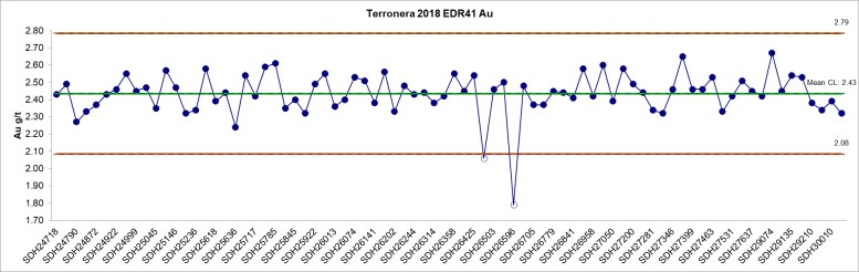
Figure 11-2 Control Chart for Gold Assays from the CRM Sample EDR-41
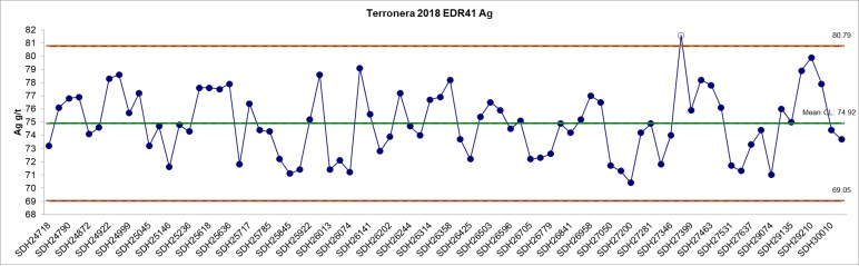
Figure 11-3 Control Chart for Silver Assays from the CRM Sample EDR-41
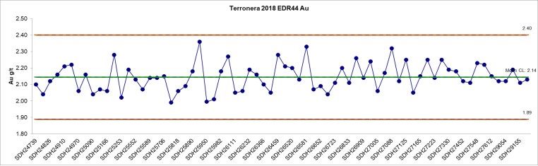
Figure 11-4 Control Chart for Gold Assays from the CRM Sample EDR-44
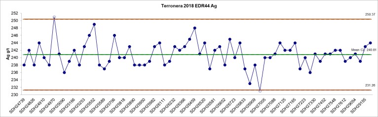
Figure 11-5 Control Chart for Silver Assays from the CRM Sample EDR-44
11.5.1 Re-Assays
A batch of 12 samples was re-analyzed at ALS Vancouver due to an EDR-41 CRM (SDH26596) greater than three standard deviations from the CL, within a mineralized zone.
Table 11-6 lists the original vs. re-assayed values of the re-analyzed batch from drill hole TR15-7 and Figure 11-6 is a scatter diagram of the original versus re-analyzed results for gold.
Table 11-6 shows similar results between the original and re-assayed samples and the scatter diagram (Figure 11-6) demonstrates a high correlation coefficient (0.98), indicating that the original results are reliable.
Table 11-6 Comparative Table of Original vs. Re-assay Values For Drill Hole TR15-7
Sample | ALS Au (g/t) | ALS Ag (g/t) | Re-assay ALS Au (g/t) | Re-assay ALS Ag (g/t) | Control Sample |
SDH26591 | 0.12 | 1.7 | 0.12 | 1.7 |
|
SDH26592 | <0.005 | <0.2 | <0.005 | <0.2 |
|
SDH26593 | 0.14 | 6.0 | 0.19 | 6.4 |
|
SDH26594 | <0.005 | 16.1 | 0.27 | 16.5 |
|
SDH26595 | 0.15 | 3.5 | 0.22 | 3.4 |
|
SDH26596 | 1.79 | 74.5 | 2.35 | 72.4 | EDR-41 |
SDH26597 | 0.04 | 10.9 | 0.29 | 11.3 |
|
SDH26598 | 0.07 | 1.7 | 0.11 | 1.7 |
|
SDH26599 | 0.04 | 1.1 | 0.07 | 1.4 |
|
SDH26600 | 0.01 | 0.8 | 0.01 | 0.7 |
|
SDH26601 | 0.01 | 0.9 | 0.01 | 0.8 |
|
SDH26602 | 0.19 | 71.0 | 0.20 | 66.3 |
|
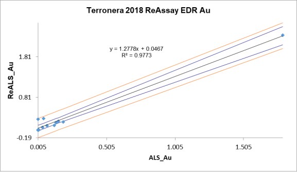
Figure 11-6 Performance of Re-assayed ALS Samples for Gold
11.6 Duplicate Samples
Crushed field duplicate samples were used to monitor the potential for sample swaps and data precision. Duplicate core samples were prepared by Endeavour Silver personnel at the core storage facility at the Terronera Project.
Preparation involved the random selection of a sample interval to be duplicated and, at the time of sampling, this interval was sawn in half using a saw or manual cutter. One half of this interval was then selected for sampling and was manually crushed using a hammer. The crushed sample was then mixed and divided by hand into two samples.
The original and duplicate samples were tagged with consecutive sample numbers and sent to the laboratory as separate samples. Duplicate samples were collected at a rate of one in 20 samples.
A total of 139 duplicate samples were taken, representing 4.6% of the total samples.
For the duplicate samples, graphical analysis shows good correlation coefficient for gold (>0.88) and excellent correlation coefficient for silver (>0.99). The results of the duplicate sampling are shown in Figure and Figure 11-8.
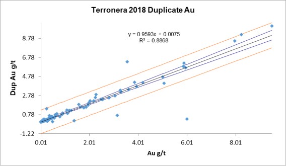
Figure 11-7 Performance of Crushed Field Duplicates for Gold
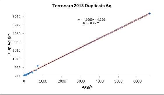
Figure 11-8 Performance of Crushed Field Duplicates for Silver
11.7 Performance of Blank Material
Blank samples were inserted to monitor possible contamination during the preparation process and analysis of the samples in the laboratory. The blank material comes from a non-mineralized rhyolite quarry located on the road from the town of La Estancia to the town of Santiago de Los Pinos. The results of previous sampling show that the values are below the detection limit (<0.005 g/t Au and <0.2 g/t Ag) and thus adequate to be used in the exploration programs. Blank samples are inserted randomly into the sample batch and given unique sample numbers in sequence with the other samples before being shipped to the laboratory.
Blank samples were inserted at an average rate of approximately one in 20 samples, with a total of 154 blank samples (5.1%) submitted.
The tolerance limit for the blank samples is 10 times the lower detection limit for the corresponding assay method (gold = 0.05 g/t and silver = 2 g/t).
Results for the blank samples are presented in Figure 11-9 and Figure 11-10.
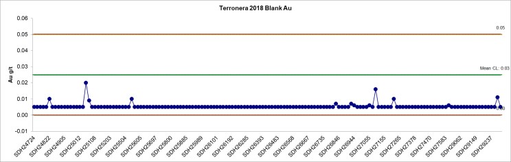
Figure 11-9 Control Chart for Gold Blank Samples
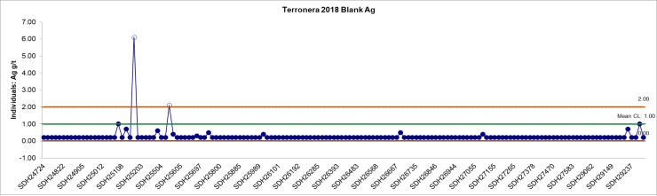
Figure 11-10 Control Chart for Silver Blank Samples
Table 11-7 Comparative Table of Original Vs. Re-Assay Values for Drill Holes TR11-4 and TR11-8
Sample Number | ALS Au (g/t) | ALS Ag (g/t) | Re-assay ALS Au (g/t) | Re-assay ALS Ag (g/t) | Control Sample |
SDH25155 | 1.62 | 1,615 | 1.79 | 1,605 |
|
SDH25156 | 1.62 | 1,945 | 1.70 | 1,935 |
|
SDH25157 | 1.77 | 6,660 | 3.23 | 6,650 |
|
SDH25158 | 1.51 | 7,300 | 3.07 | 7,330 |
|
SDH25159 | 2.21 | 2,300 | 2.19 | 2,320 |
|
SDH25160 | 0.12 | 153 | 0.13 | 157 |
|
SDH25161 | 0.06 | 92 | 0.06 | 79 |
|
SDH25162 | 0.21 | 162 | 0.23 | 167 |
|
SDH25163 | 1.75 | 1,600 | 1.74 | 1,575 |
|
SDH25164 | 1.27 | 1,170 | 1.29 | 1,165 |
|
SDH25165 | 0.59 | 527 | 0.58 | 524 |
|
SDH25167 | 2.30 | 1,830 | 2.44 | 1,810 |
|
SDH25168 | 0.02 | 15 | 0.03 | 14 |
|
SDH25169 | 1.31 | 1,780 | 1.34 | 1,730 |
|
SDH25170 | 0.50 | 275 | 0.49 | 262 |
|
SDH25171 | 0.54 | 701 | 0.56 | 700 |
|
SDH25172 | <0.005 | 6 | <0.005 | 4 | BLANK |
SDH25173 | 0.06 | 35 | 0.06 | 30 |
|
SDH25174 | 0.02 | 10 | 0.02 | 9 |
|
SDH25175 | 0.04 | 15 | 0.04 | 12 |
|
SDH25176 | 0.05 | 13 | 0.05 | 12 |
|
SDH25177 | 0.04 | 9 | 0.05 | 9 |
|
SDH25178 | <0.005 | <0.2 | <0.005 | <0.2 |
|
SDH25179 | 0.03 | 15 | 0.03 | 8 |
|
SDH25180 | 0.04 | 16 | 0.04 | 17 |
|
SDH25181 | 0.02 | 14 | 0.03 | 13 |
|
SDH25182 | 0.08 | 57 | 0.08 | 58 |
|
SDH25183 | 0.08 | 59 | 0.07 | 46 |
|
SDH25184 | 0.03 | 3 | 0.03 | 3 |
|
SDH25539 | 0.27 | 112 | 0.25 | 117 |
|
SDH25540 | 3.55 | 725 | 3.54 | 693 |
|
SDH25541 | 6.33 | 1,140 | 5.93 | 1,055 |
|
SDH25542 | 4.88 | 4,090 | 4.66 | 3,700 |
|
SDH25543 | 0.30 | 94 | 0.17 | 74 |
|
SDH25544 | 0.10 | 24 | 0.07 | 22 |
|
SDH25545 | 3.18 | 1,130 | 3.87 | 999 |
|
SDH25546 | 0.01 | 2 | <0.005 | 1 | BLANK |
SDH25547 | 7.12 | 3,140 | 6.22 | 3,140 |
|
SDH25548 | 11.20 | 2,940 | 9.60 | 3,000 |
|
SDH25549 | 3.38 | 1,220 | 2.81 | 1,040 |
|
SDH25550 | 5.69 | 3,760 | 4.86 | 3,340 |
|
SDH25551 | 4.64 | 2,290 | 4.22 | 2,100 |
|
11.7.1 Re-Assays
For gold, no blank samples returned values above the detection limit and for silver only two samples (SDH25172 & SDH25546) were outside the tolerance limit. Two batches, totalling 42 samples, were re-analyzed and the results of the original vs. the re-assays show a high correlation coefficient (>0.99) which indicates that the original values are acceptable.
The scatter diagram of silver shown in Figure 11-11 and Table 11-8 show the original vs. re-assays values of the re-analysed batches (Holes TR11-4 and TR11-8).
Due to only two samples being outside the recommended value and the results of the reanalysis being positive, it is considered that the assay results for the drilling programs are free of any significant contamination.
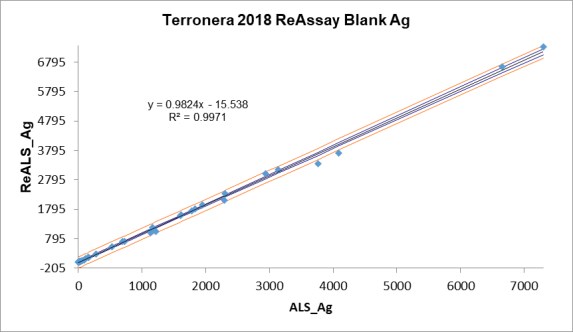
Figure 11-11 Performance of Re-assayed ALS Samples for Silver
Table 11-8 Comparative Table of Original vs. Re-assay Values for Drill Holes TR11-4 and TR11-8
Sample Number | ALS Au (g/t) | ALS Ag (g/t) | Re-assay ALS Au (g/t) | Re-assay ALS Ag (g/t) | Control Sample |
SDH25155 | 1.62 | 1,615 | 1.79 | 1,605 |
|
SDH25156 | 1.62 | 1,945 | 1.70 | 1,935 |
|
SDH25157 | 1.77 | 6,660 | 3.23 | 6,650 |
|
SDH25158 | 1.51 | 7,300 | 3.07 | 7,330 |
|
SDH25159 | 2.21 | 2,300 | 2.19 | 2,320 |
|
SDH25160 | 0.12 | 153 | 0.13 | 157 |
|
SDH25161 | 0.06 | 92 | 0.06 | 79 |
|
SDH25162 | 0.21 | 162 | 0.23 | 167 |
|
SDH25163 | 1.75 | 1,600 | 1.74 | 1,575 |
|
SDH25164 | 1.27 | 1,170 | 1.29 | 1,165 |
|
SDH25165 | 0.59 | 527 | 0.58 | 524 |
|
SDH25167 | 2.30 | 1,830 | 2.44 | 1,810 |
|
Sample Number | ALS Au (g/t) | ALS Ag (g/t) | Re-assay ALS Au (g/t) | Re-assay ALS Ag (g/t) | Control Sample |
SDH25168 | 0.02 | 15 | 0.03 | 14 |
|
SDH25169 | 1.31 | 1,780 | 1.34 | 1,730 |
|
SDH25170 | 0.50 | 275 | 0.49 | 262 |
|
SDH25171 | 0.54 | 701 | 0.56 | 700 |
|
SDH25172 | <0.005 | 6 | <0.005 | 4 | BLANK |
SDH25173 | 0.06 | 35 | 0.06 | 30 |
|
SDH25174 | 0.02 | 10 | 0.02 | 9 |
|
SDH25175 | 0.04 | 15 | 0.04 | 12 |
|
SDH25176 | 0.05 | 13 | 0.05 | 12 |
|
SDH25177 | 0.04 | 9 | 0.05 | 9 |
|
SDH25178 | <0.005 | <0.2 | <0.005 | <0.2 |
|
SDH25179 | 0.03 | 15 | 0.03 | 8 |
|
SDH25180 | 0.04 | 16 | 0.04 | 17 |
|
SDH25181 | 0.02 | 14 | 0.03 | 13 |
|
SDH25182 | 0.08 | 57 | 0.08 | 58 |
|
SDH25183 | 0.08 | 59 | 0.07 | 46 |
|
SDH25184 | 0.03 | 3 | 0.03 | 3 |
|
SDH25539 | 0.27 | 112 | 0.25 | 117 |
|
SDH25540 | 3.55 | 725 | 3.54 | 693 |
|
SDH25541 | 6.33 | 1,140 | 5.93 | 1,055 |
|
SDH25542 | 4.88 | 4,090 | 4.66 | 3,700 |
|
SDH25543 | 0.30 | 94 | 0.17 | 74 |
|
SDH25544 | 0.10 | 24 | 0.07 | 22 |
|
SDH25545 | 3.18 | 1,130 | 3.87 | 999 |
|
SDH25546 | 0.01 | 2 | <0.005 | 1 | BLANK |
SDH25547 | 7.12 | 3,140 | 6.22 | 3,140 |
|
SDH25548 | 11.20 | 2,940 | 9.60 | 3,000 |
|
Sample Number | ALS Au (g/t) | ALS Ag (g/t) | Re-assay ALS Au (g/t) | Re-assay ALS Ag (g/t) | Control Sample |
SDH25549 | 3.38 | 1,220 | 2.81 | 1,040 |
|
SDH25550 | 5.69 | 3,760 | 4.86 | 3,340 |
|
SDH25551 | 4.64 | 2,290 | 4.22 | 2,100 |
|
11.8 Check Assays
Endeavour Silver routinely conducts check analyses at a secondary laboratory to evaluate the accuracy of the primary laboratory.
Random pulps were selected from original core samples and sent to a second laboratory to verify the original assays and monitor any possible deviation due to sample handling and laboratory procedures.
For 2018, Endeavour Silver used the SGS de México laboratory in Durango, Mexico (SGS Durango), for check analyses. SGS Durango holds an ISO/IEC 17025 accreditation and is independent of Endeavour Silver
A total of 148 pulps were sent to SGS Durango for check analysis equating to approximately 4.9% of the total samples taken during the drilling program.
Correlation coefficients are high, at >0.95 for both gold and silver, showing excellent overall agreement between the original ALS Vancouver assay and the SGS Durango check assay.
The results of the check sampling program are shown by way of scatter diagrams in Figure 11-12 and Figure 11-13.
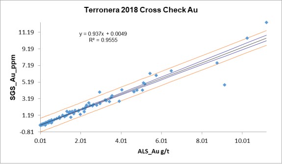
Figure 11-12 Performance of SGS Durango Check Assays for Gold
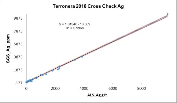
Figure 11-13 Performance of SGS Durango Check Assays for Silver
12.1 Database Verification
P&E conducted verification of the drill hole assay database by comparison of the database entries with the assay certificates, which were sent to P&E in digital format directly from ALS Vancouver.
Assay data from June 2016 through August 2018 were verified for the Terronera Project. For the La Luz deposit, 97.5% (1,435 out of 1,472) of the constrained drilling assay data were checked for both gold and silver, against the ALS laboratory certificates. No errors were identified in the database. For the Terronera deposit, 97.4% (3,128 out of 3,213) of the constrained drilling assay data for the holes drilled since 2016 were checked for both gold and silver, against the ALS Vancouver laboratory certificates. No errors were identified in the database.
12.2 P&E Site Visits and Independent Sampling
The Terronera Project site was most recently visited by Mr. David Burga, P.Geo., on January 8th and 9th, and October 16th and 17th, 2018 for the purposes of completing due diligence on sampling. During the site visit, Mr. Burga viewed access to the project area, drill hole collar locations, geology and topography, and took several global positioning system (GPS) readings to confirm the location of the baseline grid intersections and locate several drill hole collars.
During the January 2018 trip, Mr. Burga collected 12 core samples from 10 drill holes from the La Luz vein area, and three core samples from two drill holes from the Terronera vein area. During the October 2018 trip, Mr. Burga collected 10 core samples from nine drill holes from the Terronera vein area.
Drill core is stored at a company warehouse on the site where verification samples were collected by cutting the split core for each sample interval selected by Mr. Burga. One half of the resulting ¼ core sample was placed into a plastic bag into which the blank sample tag was placed. The remaining ¼-core was returned to the core box. The samples were bagged and taken directly by Mr. Burga to a DHL courier office in Puerto Vallarta for shipping to ALS in Hermosillo, Mexico, where they were received and weighed before being sent to ALS Vancouver for sample preparation and analysis.
Samples at ALS Vancouver were analyzed for gold by FA with an AAS finish and for silver by aqua regia digestion with an ICP-AES finish. Silver samples returning assay values greater than 100 g/t Ag were further analyzed by FA with a gravimetric finish. All samples were analyzed at ALS Vancouver to determine the bulk density.
Results of the January 2018 verification samples for gold and silver are presented in Figure 12-1 through Figure 12-4. Results from the October 2018 verification samples for gold and silver are presented in Figure 12-5 and Figure 12-6.
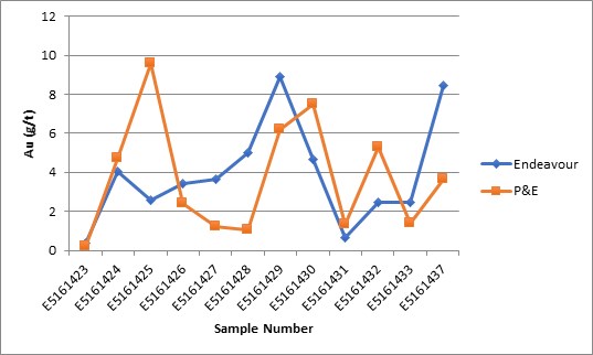
Figure 12-1 Results of La Luz Verification Sampling for Gold by P&E – January 2018
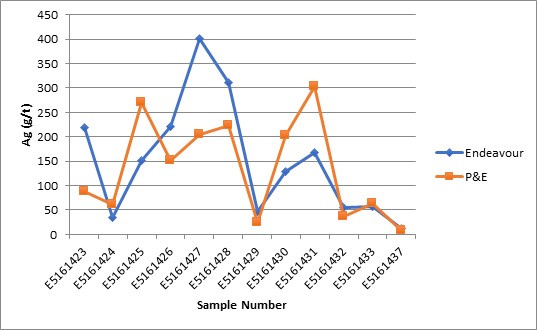
Figure 12-2 Results of La Luz Verification Sampling for Silver by P&E – January 2018
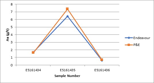
Figure 12-3 Results of Terronera Verification Sampling for Gold by P&E – January 2018
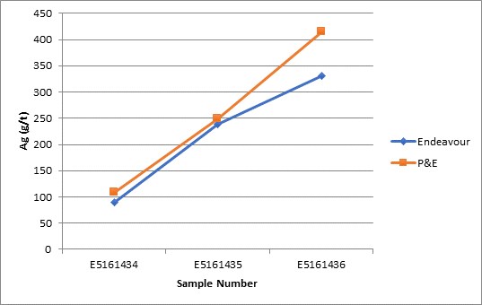
Figure 12-4 Results of Terronera Verification Sampling for Silver by P&E – January 2018

Figure 12-5 Results of Terronera Verification Sampling for Gold by P&E – October 2018
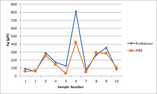
Figure 12-6 Results of Terronera Verification Sampling for Silver by P&E – October 2018
P&E considers there to be good correlation between the majority of P&E’s independent verification samples analyzed by ALS and the original analyses in the Terronera and La Luz database. Grade variation is evident in some samples, however, the QPs considers the due diligence results to be acceptable.
Based upon the evaluation of the QA/QC program undertaken by Endeavour Silver and P&E’s due diligence sampling, it is P&E’s opinion that the results are acceptable for use in Mineral Resource estimation.
13 Mineral Processing and Metallurgical Testing
There have been a number of testwork phases conducted between 2017 and 2020. The 2017-2019 work programs were supervised by Process Engineering LLC. The 2020 testwork was supervised by Ausenco.
13.1 Summary of Historical Metallurgical Testwork
13.1.1 Metallurgical Samples
The 2017-2019 metallurgical testwork included evaluation of the flotation parameters for one composite representing an average grade (gold and silver grades) of the deposit as well as three variability composite samples representing low, medium and high-grade material identified in the deposit.
The following lists the samples that were evaluated in the historical metallurgical test program:
• TR2015 – 1 Average Grade
• TR2016 – 03 Low Grade
• TR2016 – 01 Medium Grade
• TR2016 – 02 High Grade
Approximately 20 kg of each of the three variability samples (low-grade, mid-grade, high-grade) listed above were crushed to 100% passing 6 mesh, blended, and split into 1 kg charges. A representative sample was pulverized and submitted for head analyses; analyses are provided in Table 13-1.
Table 13-1 Samples Characterization and Head Assay, Fire Assay, and Whole Rock Analysis (%)
Ore Grade | Sample | Head Assays | ||||||
Au (g/t) | Ag (g/t) | SiO2 (% ) | CaO (% ) | Fe2O3 (% ) | Total S (% ) | Sulfide (% ) | ||
Average | TR2015-1 | 1.124 | 225.0 | – | – | – | 0.39 | 0.23 |
Low (LG) | TR2016-03 | 0.967 | 115.7 | 89.2 | 4.6 | 1.08 | 0.45 | 0.18 |
Medium (MG) | TR2016-01 | 2.014 | 241.4 | 84.8 | 5.6 | 1.13 | 0.24 | 0.05 |
High (HG) | TR2016-02 | 3.734 | 881.3 | 92 | 1.13 | 1.49 | 0.99 | 0.57 |
The composite samples used in the historical metallurgical test program, provided by Endeavour Silver, were considered to be representative of materials with various precious metal grades present at Terronera. The following observations were made:
• The whole rock analyses showed some variability from sample to sample for the same ore composite.
• The low and medium-grade composites showed lower quartz contents when compared to the high-grade composite.
• Differences were observed in the calcium oxide and sulphide contents as well.
• Iron content is higher in the high-grade composite.
• Higher levels of iron and sulphide provide an indication of pyrite in the high-grade composite.
Although samples included in the 2017-2019 testwork program represented the range of anticipated ore grades (gold and silver grades) in the Terronera deposits, no specific variability samples with respect to the various lithologies, geometallurgical domains or spatial distribution within the deposit were tested.
Of note, approximately 81.9% of the gold and 89.3% of the silver present in the average grade sample were determined to be cyanide soluble by amenability testing, results of which are provided in Table 13-2.
Table 13-2 Cyanide Solubility of Composite Sample TR2015-1
Element (units) | Assay | Assay | Cyanide Soluble, % |
Cyanide soluble gold (g/t Au) | 1.12 | 0.92 | 81.9 |
Cyanide soluble silver (g/t Ag) | 225 | 201 | 89.3 |
13.1.2 Comminution Testing
The 2017-2019 metallurgical test program provided a Bond Ball Mill Work Index (BWi) for four samples (501, 502, 503 and 504 shown in Table 13-3) from various areas of the deposit. Each sample was tested at a closed size of 100 mesh. In addition, the BWi was determined for the original average grade composite sample (TR 2015-1) at a closed size of 100 and 200 mesh. The BWi results obtained in previous test programs are summarized in Table 13-3.
Table 13-3 Bond Ball Mill Work Index Test Results
Sample | BWi @100 mesh (kWh/t) |
501 | 15.82 |
502 | 16.98 |
503 | 16.73 |
504 | 17.65 |
TR 2015-1 | 17.36 |
Sample | BWi @200 mesh (kWh/t) |
TR 2015-1 | 17.28 |
Some of the samples listed in Table 13-3 were submitted to Hazen Research for additional comminution testing. The samples were subjected to SMC testing, Bond rod mill work index (RWi), Bond abrasion index (Ai), and Bond impact work index testing (CWi), the results of which are provided in Table 13-4.
Table 13-4 Comminution Testing Results
RWi (kWh/t) | Ai (g) | CWi (kWh/t) | SCSE (kWh/t) |
17.2 | 1.0916 | 8.3 | 9.85 |
Note: SCSE = standard circuit specific energy
The comminution testing indicated that the material would be classified as hard and highly abrasive.
13.1.3 Primary Grind Size and Deleterious Elements
The three grade variability samples were subjected to rougher flotation testing at three different grind sizes including 80% passing 150, 200 and 270 mesh (Tyler) and the primary grind size of 100 µm was determined.
Deleterious elements detected in the ICP scan conducted on the final concentrate product in the 2017-2019 test programs indicated that trace amount of arsenic, cadmium, chromium, mercury and antimony were present. These elements have the potential to affect the marketability and price of the final concentrate product. Thus, further flotation studies need to be conducted on variability samples containing various levels of deleterious elements, to understand the concentration of such elements in the final flotation concentrate product.
13.1.4 Solid-Liquid Separation Testing
Pocock Industrial (Pocock) conducted solids liquid separation (SLS) tests on two samples (Flotation Tails and Flotation Concentrate materials) in the year 2016. The testwork was managed by Process Engineering LLC. The samples were generated at Resource Development Inc. (RDI) in Wheat Ridge, Colorado and shipped to Pocock Industrial’s laboratory in Salt Lake City, Utah for SLS testing. The overall objective of the test program was to develop a general set of data for design of thickening and filtration equipment to dewater the material prior to further processing or final disposal.
Prior to conducting formal equipment sizing procedures, flocculant screening tests were performed on each sample. These tests aided in the selection of flocculants able to provide the best overall performance with respect to overflow clarity, decantation rates, and underflow viscosity characteristics for each material. Static thickening tests were then performed for each material to develop a general data set for conventional thickener design. Following static testing, dynamic thickening tests developed a general set of data for high-rate thickener design (for the tails material only, due to lack of concentrate solids provided). Dynamic testing also provided overflow suspended solids concentration estimates for design. Furthermore, pulp consolidation tests performed on thickening test underflow sought to simulate the dewatering characteristics of each material in tailings dam lift.
Viscosity tests performed on samples of underflow generated from the thickening tests evaluated the rheological properties of each material for rake mechanism and underflow pipeline design. These tests also served to establish the maximum recommended design underflow density for each thickener type (conventional and highrate). Finally, vacuum and pressure filtration tests performed on specified samples of thickened underflow established a general set.
Table 13-5 Summary of Fully Automatic Membrane Type Filter Press
Material | Feed Solids Conc. | Sizing Basis (dry m3/MT) | Cake Thickness (mm) | Design Cake Moisture | Total Cycle Time (min) | Volumetric Production Rate (MTPD/m3) | Area Basis Production Rate (MTPD/m2) |
Thickened Flotation Tails | 67.0% | 0.797 | 40 | 12.0% | 9.0 | 167.29 | 2.92 |
Thickened Flotation Concentrate | 63.5% | 0.638 | 40 | 15.2% | 13.39 | 140.46 | 2.45 |
Pressure filtration tests examined the effect of cake thickness, and air-dry duration on production rate, and filter cake moisture for the thickened materials. The samples were tested at the solids concentrations expected in the plant.
Achieved pressure filtration production rates ranged from 2.92 MTPD/m2 for the Flotation Tails material to 2.45 MTPD/m2 for the Flotation Concentrate material.
13.1.5 New Metallurgical Testing
The 2017-2019, and 2020 metallurgical testwork results formed the basis of the 2020 UPFS process design, using the additional metallurgical testing to define primary grind size and flotation circuit design parameters, as well as develop new recovery models.
As part of the 2020 UPFS testwork on the Terronera Project, additional metallurgical tests were conducted at the ALS Metallurgy facility in Kamloops, B.C. The various samples used in this most recent test program were obtained in 2019, prepared from drill core considered to be representative of the mine life. The 2019-2020 test program completed include grind versus recovery, flash flotation, and cleaner circuit confirmation testing with the goal of economically refining the process plant design parameters and flowsheets to be used in the 2020 UPFS.
The 2020 metallurgical testwork was completed using the following composite samples: Terronera MC1, Terronera MC2, High S MC, and Low S MC. These master composite samples were formed based on spatial distribution and sulphur grades. It is anticipated that the Feasibility study phase of the project will test a broader suite of samples under the preferred process conditions to evaluate metallurgical responses between and within the two deposits (Terronera and La Luz).
Table 13-6 2020 Test Samples Head Assays
Head Assays | ||||
Sample Description | Au (g/t) | Ag (g/t) | Fe (%) | S (%) |
Terronera MC1 | 3.6 | 172.0 | 1.2 | 0.35 |
Terronera MC2 | 2.17 | 231.0 | 1.4 | 0.43 |
Low S MC | 3.36 | 283.0 | 0.9 | 0.05 |
High S MC | 1.68 | 1450 | 2.0 | 1.87 |
No additional comminution testing was completed as part of the 2020 metallurgical test program. It is anticipated that additional testwork will be completed in the Feasibility phase of the project to confirm the results achieved in historical test programs and further define the variability of the ore across the deposit.
13.1.6 Flotation Testwork
Primary grind vs recovery tests were completed as part of the 2020 testwork to compare the rougher flotation stage recoveries at three different grind sizes of 80% passing of 70 to 135 μm. The relationship between grind size and silver/gold recovery shows similar trends for both high- and low-grade samples in Figure 13-1. The rougher flotation recovery benefits of silver/gold outweigh grinding mill capital and operating cost savings at 70 μm. Thus, the primary grind size of 70 μm was chosen as the basis of design for the UPFS.
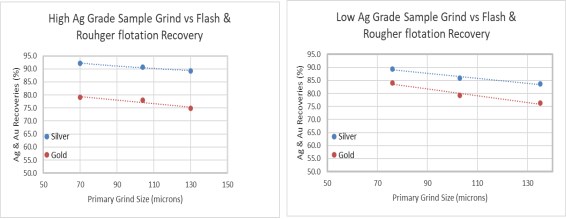
Source: Ausenco, June 2020
Figure 13-1 High- and Low-grade Grind Size vs 2020 Metallurgical Testwork Recovery
Cleaner flotation circuit confirmation tests were conducted to examine the possibility of removing the regrind mill and reduction of cleaner circuit stages to achieve the minimum target silver grade of 4,500 g/t in the final concentrate. Two cleaner circuit locked cycle tests (LCT), using low- and high-grade samples, achieved concentrate silver grades higher than 4,500 g/t without the aid of a regrind mill.
The lower feed grade sample still required two stages of cleaners to achieve the minimum silver target concentrate grade.
13.2 New Recovery Model
The process flowsheet adopted for the 2020 UPFS includes three-stage crushing followed by closed circuit grinding to achieve a flotation feed particle size of 80% passing 70 µm. A flash flotation operation was included to improve the recovery of precious metals in coarse particles. In the 2017-2019 testwork, incorporation of a regrind circuit had been included, however, the -2020 testwork indicated that the regrind circuit was not required to exceed the target silver concentrate grades of 4,500 g/t and thus it has been removed in the current design.
Revised silver and gold recovery models were developed using 2019/2020 LCT data as shown in Figure 13-2 and Figure 13-3. More metallurgical testwork is recommended to assess ore variability in the next study phase. Figure 13-2 shows the recovery estimation between 150 g/t and 300 g/t Ag feed grade. Separate flash and conventional flotation circuit recoveries are shown in the recovery model.
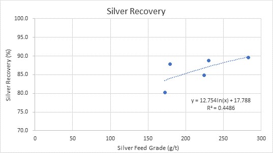
Source: Ausenco, June 2020
Figure 13-2 Silver Recovery Model
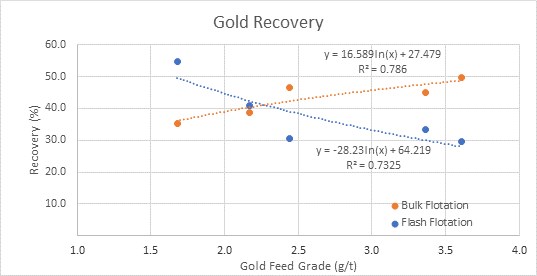
Source: Ausenco, June 2020
Figure 13-3 Gold Recovery Model
The estimated recoveries are 84.9% Ag and 82.3% Au for LOM feed grades, respectively. The gold and silver recoveries range from 80.7 to 83.1% and 80.3 to 88% throughout the mine life. The recovery estimates are at a target grind particle size of 80% passing 70 µm.
The bulk of the testwork was completed on Terronera ore as it is the most significant component of the feed to the mill over the life-of-mine (LOM). Limited testwork was conducted on the La Luz ores; however, the available results indicated higher metallurgical recoveries than those obtained on Terronera ores, and thus Terronera material has been used as the basis of the design.
14 Mineral Resource Estimates
The Terronera and La Luz deposits are discussed separately regarding their Mineral Resource Estimates.
14.1 Terronera Deposit Mineral Resource Estimate
14.1.1 Introduction
This Updated Technical Report section is to update the Mineral Resource estimate on the Preliminary Feasibility Study for the Terronera deposit of Endeavour Silver, dated September 18, 2018. The Mineral Resource estimate presented herein is reported in accordance with the Canadian Securities Administrators’ National Instrument 43-101 and has been estimated in conformity with generally accepted CIM « Estimation of Mineral Resources and Mineral Reserves Best Practices » guidelines. Mineral Resources are not Mineral Reserves and do not have demonstrated economic viability. There is no guarantee that all or any part of the Mineral Resource will be converted into a Mineral Reserve. Confidence in the estimate of Inferred Mineral Resources is insufficient to allow the meaningful application of technical and economic parameters or to enable an evaluation of economic viability worthy of public disclosure. Mineral Resources may be affected by further infill and exploration drilling that may result in increases or decreases in subsequent Mineral Resource estimates.
This Mineral Resource estimate was undertaken by Yungang Wu, P.Geo., and Eugene Puritch, P.Eng., FEC, CET of P&E Mining Consultants Inc., Brampton, Ontario, both independent Qualified Persons in terms of NI 43-101, from information and data supplied by Endeavour Silver. The effective date of this Mineral Resource estimate is February 1, 2019.
14.1.2 Database
All drilling and assay data were provided in the form of Excel data files by Endeavour Silver. The Gems database for this Mineral Resource estimate, constructed by P&E, consisted of 195 drill holes totalling 65,083 m and 36 channel samples totalling 77.25 m, of which 39 drill holes totalling 18,774 m were drilled in 2018 (Table 14-1). A drill hole plan is shown in Figure 14-1.
Table 14-1 Terronera Drill Hole Database Summary
Drilling Year | No. of Drill Holes | Drilling (m) | No. of Samples | Notes |
2018 | 39 | 18,773.65 | 2,545 | Used for this Mineral Resource update |
2017 | 18 | 7,817.05 | 1,184 | Used for Mineral Resource estimate dated August 7, 2018 |
2011-2016 | 138 | 38,492.25 | 12,943 | Used for Mineral Resource estimate dated August 7, 2018 |
Total | 195 | 65,082.95 | 16,672 | Used for this Mineral Resource estimate |
Channel Samples | 36 | 77.25 | 63 | Used for Mineral Resource estimate dated August 7, 2018 |
Coordinate system: WGS 84 / UTM Zone 13Q
Figure 14-1 Terronera Surface Drill Hole Plan
The assay table of the Mineral Resource estimate database contained a total of 16,672 assays for Au, Ag, Cu, Pb, Zn, etc. from drill holes and 63 assays from channel samples. The Au and Ag assays were factored downward by core recovery and were marked as Au_REC and Ag_REC in the database which was utilized for the Mineral Resource estimate.
All drill hole survey and assay values are expressed in metric units, while grid coordinates are in the WGS84, Zone 13Q UTM geodetic reference system.
14.1.3 Data Verification
P&E carried out data verification for silver and gold assays contained in the Mineral Resource wireframes against laboratory certificates that were obtained directly from ALS Chemex laboratory in Hermosillo, Mexico. Over 95% were checked with no errors were found.
Endeavour Silver adjusted downward 1,720 raw Ag and Au assays for core recovery, of which 415 of these assays were used for the Mineral Resource estimate. For example, if core recovery was 92%, the Ag and Au assay values were reduced to 92% of the original analytical value. The adjusted values are recorded in the database as « Ag_REC » and « Au_REC » and these values were used for the Mineral Resource estimate. P&E’s site visit confirmed that core recovery was generally very good, the vein was very competent, and recovery was over 90% for the core examined. The oxidation level was generally low, and the mineralization appeared unleached. P&E agrees with Endeavour Silver that the use of « recoverable » grades is a conservative approach.
In addition to the data verification reported above, P&E reviewed the QAQC for the Terronera Project analyses and concludes that the analyses are acceptable. In P&E’s opinion the drill hole and assay/analytical databases may be used for the estimation of Mineral Resources.
14.1.4 Domain Interpretation
A total of eight (8) mineralized vein wireframes were generated during of this Mineral Resource estimate. A cut-off grade of 150 g/t silver equivalent (AgEq) was applied to the wireframes. The AgEq was calculated with a formula of AgEq=Ag + (Au x 75). The wireframes were created from successive polylines looking N40W (AZ 320) orientated on vertical cross-sections with a 25 m spacing. Minimum constrained sample length for interpretation was 2.0 m. In some cases, mineralization below the above mentioned 150 g/t AgEq cut-off was included for the purpose of maintaining zonal continuity and the minimum width. On each cross-section, polyline interpretations were digitized from drill hole to drill hole but not typically extended more than 25 m into untested territory. Historical mined out areas were depleted from the Terronera Vein with shapes of historical stopes provided by Endeavour Silver. P&E did not verify the shape of these stopes.
The resulting wireframe 3-D domains were used as hard boundaries during Mineral Resource grade estimation, for rock coding of the block model, statistical analysis and compositing limits. The 3-D domains are presented in Figure 14-2.
A topographic surface was provided by Endeavour Silver. The topographic surface was created using a satellite image which presented some discrepancies with the surveyed drill hole collars. The Mineral Resource estimate influenced by these discrepancies is minor; however, it is recommended that Endeavour Silver should survey the topography of the Terronera Deposit in the future.

Figure 14-2 Terronera Deposit 3-D Domains and Wireframes
14.1.5 Model Rock Code Determination
A unique model rock code was assigned for blocks within each mineralized domain in the Mineral Resource estimate model. The codes applied for the models are tabulated in Table 14-2.
Table 14-2 Model Rock Code Description and Volume
Domains | Rock Type | Volume (m3) |
Terronera Vein | 100 | 2,415,651 |
HW1 | 200 | 348,691 |
HW2 | 300 | 145,444 |
HW3 | 400 | 18,007 |
HW4 | 500 | 30,127 |
HW5 | 600 | 68,139 |
HW6 | 700 | 35,860 |
FW | 800 | 71,256 |
Air | 0 |
|
Waste | 99 |
|
Note: HW = hanging wall, FW = footwall
14.1.6 Compositing
The basic statistics of all constrained assays and sample length are presented in Table 14-3.
Table 14-3 Basic Statistics of All Constrained Assays and Sample Length
Variable | Ag_REC | Ag | Au_REC | Au | Length (m) |
Number of Samples | 2,649 | 2,649 | 2,649 | 2,649 | 2,649 |
Minimum Value (g/t) | 0.30 | 0.30 | 0.008 | 0.008 | 0.10 |
Maximum Value (g/t) | 15,532.50 | 15,532.50 | 36.50 | 36.50 | 4.00 |
Mean (g/t) | 275.05 | 289.39 | 2.11 | 2.23 | 0.71 |
Median (g/t) | 81.80 | 90.00 | 0.93 | 1.03 | 0.60 |
Geometric Mean (g/t) | 81.73 | 89.65 | 0.79 | 0.87 | 0.62 |
Variance | 701,066.35 | 718,739.91 | 11.26 | 11.81 | 0.15 |
Standard Deviation (g/t) | 837.30 | 847.79 | 3.36 | 3.44 | 0.39 |
Coefficient of Variation | 3.04 | 2.93 | 1.59 | 1.54 | 0.54 |
Approximately 84% of the constrained sample lengths were 1 m or less, with an overall average of 0.71 m. To regularize the assay sampling intervals for grade interpolation, a 1.0 m compositing length was selected for the drill hole intervals that fell within the constraints of the above-mentioned domains. The composites were calculated for Ag and Au over 1.0 m lengths starting at the first point of intersection between assay data hole and hanging wall of the 3-D zonal constraint. The compositing process was halted upon exit from the footwall of the wireframe constraint. Un-assayed intervals and below detection limit assays were set to 0.001 g/t for all elements. Any composites that were less than 0.25 m in length were discarded so as not to introduce any short sample bias in the interpolation process. The constrained composite data were extracted to point files for a capping study. The composite statistics are summarized in Table 14-4.
Table 14-4 Composite Summary Statistics
Variable | Ag Composite | Au Composite | Ag Capped Composite | Au Capped Composite |
Number of Samples | 2,012 | 2,012 | 2,012 | 2,012 |
Minimum Value (g/t) | 0.001 | 0.001 | 0.001 | 0.001 |
Maximum Value (g/t) | 11,514.68 | 28.58 | 2,100.00 | 15.00 |
Mean (g/t) | 236.85 | 1.91 | 201.72 | 1.87 |
Median (g/t) | 85.99 | 0.98 | 85.99 | 0.98 |
Geometric Mean (g/t) | 81.63 | 0.81 | 80.58 | 0.81 |
Variance | 360,760.89 | 7.02 | 118,394.35 | 5.88 |
Standard Deviation (g/t) | 600.63 | 2.65 | 344.08 | 2.42 |
Coefficient of Variation | 2.54 | 1.39 | 1.71 | 1.29 |
14.1.7 Grade Capping
Grade capping was investigated on the 1.0 m composite values in the database within the constraining domains to ensure that the possible influence of erratic high values did not bias the database. Ag and Au composite Log-normal histograms were generated for each mineralized domain and the resulting graphs are exhibited in Figure 14-3 to Figure 14-8. The Ag and Au grade capping values are detailed in Table 14-5 and Table 14-6 respectively. The capped composites were utilized to develop variograms and for block model grade interpolation.
Figure 14-3 Terronera TRV Ag Composite Distribution
Figure 14-4 Terronera TRV Au Composite Distribution

Figure 14-5 Terronera HW1 Ag Composite Distribution
Figure 14-6 Terronera HW1 Au Composite Distribution
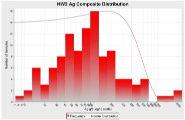
Figure 14-7 Terronera HW2 Ag Composite Distribution
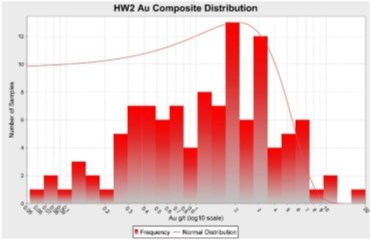
Figure 14-8 Terronera HW2 Au Composite Distribution
Table 14-5 Silver Grade Capping Values
Domains | Total No. of Composites | Capping Value Ag (g/t) | Total No. of Capped Composites | Mean | Coefficient of Variation | Capping Percentile | ||
Composites | Capped Composites | Composites | Capped Composites | |||||
Terronera Vein | 1,433 | 2,100 | 25 | 255.98 | 220.09 | 2.57 | 1.74 | 98.3% |
HW1 | 259 | 1,000 | 3 | 156.32 | 143.40 | 1.85 | 1.32 | 98.8% |
HW2 | 120 | 700 | 6 | 241.39 | 150.20 | 2.55 | 1.22 | 95.0% |
HW3 | 15 | 600 | 2 | 316.39 | 243.24 | 1.16 | 0.89 | 86.7% |
HW4 | 29 | No Capping | 0 | 106.32 | 106.32 | 1.25 | 1.25 | 100.0% |
HW5 | 57 | No Capping | 0 | 141.35 | 141.35 | 1.17 | 1.17 | 100.0% |
HW6 | 39 | No Capping | 0 | 50.09 | 50.09 | 0.88 | 0.88 | 100.0% |
FW | 61 | 1,300 | 2 | 368.24 | 286.41 | 1.91 | 1.23 | 96.7% |
Note: HW = hanging wall, FW = footwall
Table 14-6 Gold Grade Capping Values
Domains | Total No. of Composites | Capping Value Au (g/t) | Total No. of Capped Composites | Mean | Coefficient of Variation | Capping Percentile | ||
Composites | Capped Composites | Composites | Capped Composites | |||||
Terronera Vein | 1,433 | 15 | 7 | 1.89 | 1.88 | 1.30 | 1.26 | 99.5% |
HW1 | 259 | 15 | 3 | 1.96 | 1.84 | 1.74 | 1.46 | 98.8% |
HW2 | 120 | 12 | 1 | 2.08 | 2.02 | 1.31 | 1.18 | 99.2% |
HW3 | 15 | No Capping | 0 | 0.55 | 0.55 | 0.96 | 0.96 | 100.0% |
HW4 | 29 | No Capping | 0 | 1.94 | 1.94 | 1.17 | 1.17 | 100.0% |
HW5 | 57 | 10 | 1 | 1.65 | 1.54 | 1.86 | 1.68 | 98.2% |
HW6 | 39 | No Capping | 0 | 2.54 | 2.54 | 0.86 | 0.86 | 100.0% |
FW | 61 | 12 | 1 | 1.77 | 1.67 | 1.81 | 1.65 | 98.4% |
Note: HW = hanging wall, FW = footwall
14.1.8 Semi-Variography
A semi-variography study was performed as a guide to determining a grade interpolation search strategy. Omni, along strike, down dip and across dip semi-variograms were attempted for each domain using Ag and Au capped composites, see Figure 14-9 to Figure 14-13.
Continuity ellipses based on the observed ranges were subsequently generated and utilized as the basis for estimation search ranges, distance weighting calculations and Mineral Resource classification criteria. The anisotropy was modeled based on an average strike direction of 320°, -75° northeast down dip.
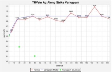
Figure 14-9 Terronera TR Vein Ag Along Strike Variogram
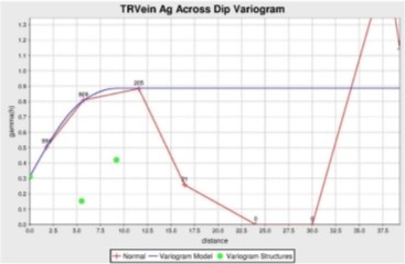
Figure 14-10 Terronera TR Vein Ag Across Dip Variogram
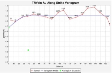
Figure 14-11 Terronera TR Vein Au Along Strike Variogram
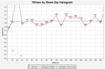
Figure 14-12 Terronera TR Vein Au Down Dip Variogram

Figure 14-13 Terronera TR Vein Au Across Dip Variogram
14.1.9 Bulk Density
A total of 2,756 bulk density measurements from 127 drill holes were provided by Endeavour Silver, of which 1,062 measurements were located within the mineralized veins. The vein constrained bulk density was averaged 2.59 t/m3 with range of 2.02 to 3.25 t/m3. The bulk density determination by Endeavour Silver was undertaken with water displacement on waxed drill core.
David Burga, P.Geo of P&E collected 15 samples during his site visits on June 14, 2016 and January 9, 2018. The samples were tested in AGAT Laboratories in Mississauga, and the average bulk density was 2.68 t/m3.
David Burga, P.Geo of P&E collected 10 samples on an October 16, 2018 site visit. The samples were tested in AGAT Laboratories in Mississauga, and the average bulk density was 2.68 t/m3.
14.1.10 Block Modeling
The Terronera Mineral Resource block model was constructed using Geovia Gems V6.8 modelling software and the block model origin and block size are tabulated in Table 14-7. The block model consists of separate models for estimated grade of Ag, Au and AgEq, rock type, volume percent, bulk density and classification attributes.
Table 14-7 Terronera Block Model Definition
Direction | Origin | No. of Blocks | Block Size (m) |
X | 516,355 | 400 | 4.0 |
Y | 2,296,905 | 280 | 1.0 |
Z | 1,760 | 168 | 4.0 |
Rotation | 50o clockwise | ||
All blocks in the rock type block model were initially assigned a waste rock code of 99, corresponding to the surrounding country rocks. All mineralized domains were used to code all blocks within the rock type block model that contain 1% or greater volume within the domains. These blocks were assigned their appropriate individual rock codes as indicated in Table 14-2. The topographic surfaces were subsequently utilized to assign rock code 0 for air, to all blocks 50% or greater above that surface.
A volume percent block model was set up to accurately represent the volume and subsequent tonnage that was occupied by each block inside the constraining domains. As a result, the domain boundary was properly represented by the volume percent model ability to measure individual infinitely variable block inclusion percentages within that domain. The minimum percentage of the mineralized block was set to 1%.
The bulk density of each block in the mineralized domains was interpolated with the Inverse Distance Squared method using 2,756 bulk density measurements.
The Ag and Au grade were interpolated with Inverse Distance Cubed (1/d3) using capped composites. Multiple passes were executed for the grade interpolation to progressively capture the sample points to avoid over smoothing and preserve local grade variability. Search ranges were based on the variograms and search directions which were aligned with the strike and dip directions of each mineralized domain accordingly. Grade blocks were interpolated using the parameters in Table 14-8.
Table 14-8 Gold and Silver Block Model Interpolation Parameters
Element | Pass | Dip Range (m) | Strike Range (m) | Across Dip Range (m) | Max. No. of Samples per Hole | Min. No. of Samples | Max. No. of Samples |
Ag | I | 27 | 30 | 6 | 2 | 5 | 12 |
II | 45 | 50 | 10 | 2 | 3 | 12 | |
III | 135 | 150 | 30 | 2 | 1 | 12 | |
Au | I | 20 | 25 | 5 | 2 | 5 | 12 |
II | 30 | 40 | 10 | 2 | 3 | 12 | |
III | 135 | 150 | 30 | 2 | 1 | 12 |
The Ag equivalent (AgEq) values were derived using the formula:
AgEq g/t = Ag g/t + (Au g/t x 75).
Selected vertical cross-sections and plans of the AgEq grade blocks are presented in section 14.1.15.1 AgEq Block Model Vertical Cross Sections and Plans.
14.1.11 Mineral Resource Classification
In P&E’s opinion, the drilling, assaying and exploration work of the Terronera deposit supporting this Mineral Resource estimate are sufficient to indicate a reasonable prospect of economic extraction and thus qualify it as a Mineral Resource under the CIM definition standards. The Mineral Resource was classified as Indicated and Inferred based on the geological interpretation, semi-variogram performance and drill hole spacing. The Indicated Mineral Resource was classified for the blocks interpolated by the grade interpolation Pass I and II in the Table 14-8, which used at least three composites from a minimum of two drill holes, and Inferred Mineral Resources were classified with Pass III for all remaining populated grade blocks within the mineralized domains. The classifications have been adjusted on a longitudinal projection to reasonably reflect the distribution of each classification. Selected classification block cross-sections and plans are attached in section 14.1.15.2 Classification Block Model Cross Sections and Plans, Terronera Deposit.
14.1.12 Mineral Resource Estimate Cut-off
The Mineral Resource estimate was derived from applying a AgEq cut-off grade to the block model and reporting the resulting tonnes and grade for potentially mineable areas.
Table 14-9 shows the rationale supporting the AgEq cut-off grade that determines the underground potentially economic portions of the constrained mineralization.
Table 14-9 Terronera Underground AgEq Cut-Off Grade Calculation
| Comments |
Au Price | US$1,275oz based on approx. 30-month trailing average at Oct 31/18 |
Ag Price | US$17.50/oz based on approx. 30-month trailing average at Oct 31/18 |
AgEq Recovery | 87% |
Mining Cost | $40/tonne mined |
Process Cost | $23/tonne mined |
General & Administration | $10/tonne mined |
AgEq Refining $/oz | $0.5 |
AgEq Smelter Payable | 99% |
Therefore, the AgEq cut-off grade for the underground Mineral Resource estimate is calculated as follows:
Mining, Processing and G&A costs per ore tonne = ($40 + $23 + $10) = $73/tonne
[($73)/[($17.50-$0.50)/31.1035 x 87% Recovery x 99% Payable] = 155.3 g/t, Use 150 g/t
14.1.13 Mineral Resource Estimate
P&E considers that the silver and gold mineralization of the Terronera Deposit is potentially amenable to underground extraction. The resulting Mineral Resource estimate is tabulated in the Table 14-10.
Table 14-10 Terronera Mineral Resource Estimate at a Cut-off Grade of 150 g/t AgEq (1-5)
Classification | Tonnage (kt) | Ag (g/t) | Contained Ag (koz) | Au (g/t) | Contained Au (koz) | AgEq (g/t) | Contained AgEq (koz) |
Indicated | 5,275 | 227.2 | 38,537 | 2.35 | 398 | 403.4 | 68,416 |
Inferred | 1,022 | 212.2 | 6,970 | 1.70 | 56 | 339.8 | 11,161 |
1. Mineral Resources which are not Mineral Reserves do not have demonstrated economic viability. The estimate of Mineral Resources may be materially affected by environmental, permitting, legal, title, taxation, socio-political, marketing, or other relevant issues.
2. The Inferred Mineral Resource in this estimate has a lower level of confidence than that applied to an Indicated Mineral Resource and must not be converted to a Mineral Reserve. It is reasonably expected that the majority of the Inferred Mineral Resource could be upgraded to an Indicated Mineral Resource with continued exploration.
3. The Mineral Resources in this report were estimated using the Canadian Institute of Mining, Metallurgy and Petroleum (CIM), CIM Standards on Mineral Resources and Reserves, Definitions and Guidelines prepared by the CIM Standing Committee on Reserve Definitions and adopted by the CIM Council.
4. AgEq g/t = Ag g/t + (Au g/t x 75)
5. Historically mined areas were depleted from the Terronera Vein wireframe.
Mineral Resources are sensitive to the selection of a reporting AgEq cut-off grade and are shown in Table 14-11.
Table 14-11 Terronera Sensitivity of Mineral Resource Estimate to AgEq Cut-off
Class-ification | Cut-Off AgEq (g/t) | Tonnage (kt) | Ag (g/t) | Contained Ag (koz) | Au (g/t) | Contained Au (koz) | AgEq (g/t) | Contained AgEq (koz) |
Indicated | 1,000 | 223 | 1,075.3 | 7,716 | 3.92 | 28.1 | 1,369.3 | 9,826 |
750 | 470 | 802.9 | 12,126 | 4.02 | 60.7 | 1,104.4 | 16,680 | |
500 | 1,183 | 517.1 | 19,671 | 3.78 | 144.0 | 800.9 | 30,468 | |
250 | 3,580 | 286.1 | 32,923 | 2.84 | 326.4 | 498.8 | 57,406 | |
200 | 4,490 | 250.7 | 36,194 | 2.57 | 370.5 | 443.2 | 63,977 | |
150 | 5,275 | 227.2 | 38,537 | 2.35 | 398.4 | 403.4 | 68,416 | |
100 | 5,898 | 210.3 | 39,874 | 2.18 | 414.2 | 374.1 | 70,937 | |
50 | 6,360 | 198.0 | 40,491 | 2.06 | 421.1 | 352.5 | 72,076 | |
0.01 | 6,533 | 193.3 | 40,595 | 2.01 | 422.1 | 344.0 | 72,256 | |
Inferred | 1,000 | 12 | 802.3 | 311 | 4.52 | 1.8 | 1,141.2 | 442 |
750 | 54 | 634.8 | 1,104 | 3.65 | 6.4 | 908.6 | 1,581 | |
500 | 169 | 490.6 | 2,673 | 2.81 | 15.3 | 701.6 | 3,823 | |
250 | 581 | 274.3 | 5,126 | 2.34 | 43.7 | 449.7 | 8,406 | |
200 | 761 | 243.3 | 5,951 | 2.04 | 50.0 | 396.5 | 9,697 | |
150 | 1,022 | 212.2 | 6,970 | 1.70 | 55.9 | 339.8 | 11,161 | |
100 | 1,264 | 186.4 | 7,575 | 1.50 | 61.0 | 298.9 | 12,150 | |
50 | 1,381 | 174.3 | 7,739 | 1.41 | 62.7 | 280.1 | 12,440 | |
0.01 | 1,413 | 171.0 | 7,768 | 1.38 | 62.8 | 274.6 | 12,477 |
14.1.14 Confirmation of Estimate
The block model was validated using several industry standard methods including visual and statistical methods.
Visual examination of composite and block grades on successive plans and cross-sections on-screen in order to confirm that the block model correctly reflects the distribution of sample grades. The review of estimation parameters included:
• Number of composites used for estimation
• Number of holes used for estimation
• Mean Distance to sample used
• Number of passes used to estimate grade
• Mean value of the composites used.
A comparison of Ag and Au mean grades of composites with block model on a global basis is presented in Table 14-12.
Table 14-12 Average Grade Comparison of Composites with Block Model
Data Type | Ag (g/t) | Au (g/t) |
Composites | 236.9 | 1.91 |
Capped Composites | 201.7 | 1.87 |
Block Model ID3* | 189.3 | 1.90 |
Block Model NN** | 189.6 | 1.92 |
* block model grade interpolated using Inverse Distance Cubed.
** block model grade interpolated using Nearest Neighbour.
The comparison above shows the average grades of the Ag and Au blocks in the block models to be somewhat lower than the average grades of capped composites used for grade estimation. This is probably due to the localized clustering were smoothed by the block modeling grade interpolation process. The block model grade will be more representative than the capped composites due to the block model’s 3-D spatial distribution characteristics.
A volumetric comparison was performed with the block model volume versus the geometric calculated volume of the domain wireframes and the differences are shown in Table 14-13.
Table 14-13 Volumetric Comparison of Block Model with Geometric Wireframes
Geometric Volume of Wireframes | 3,133,175 m3 |
Block Model Volume | 3,132,129 m3 |
Difference % | 0.03% |
Ag local trends of the main Terronera Vein domain were evaluated by comparing the ID3 and NN estimate against Ag Composites and Capped Composites (Figure 14-14 to Figure 14-16). As shown in Figure 14-14 and Figure 14-16, the Ag grade interpolation with Inverse Distance Cubed and Nearest Neighbour agreed well.
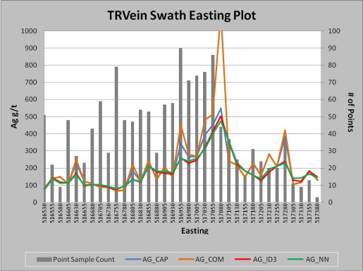
Figure 14-14 Terronera Silver Grade Swath Easting Plot
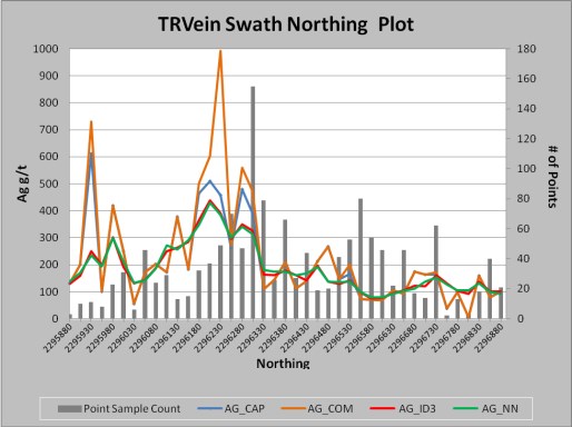
Figure 14-15 Silver Grade Swath Northing Plot
Figure 14-16 Silver Grade Swath Elevation Plot
A comparison of the grade-tonnage curve of the Ag grade model interpolated with Inverse Distance cubed (1/d3) and Nearest Neighbour (NN) on the main Terronera Vein wireframe is shown in Figure 14-17.
Figure 14-17 Silver Grade-Tonne Curve of Terronera Vein by ID3 and NN Interpolation
14.1.15 Figures and Maps Pertaining to the Mineral Resource Estimate for the Terronera Deposit
To visually understand the Terronera Deposit Mineral Resource Estimate, figures, vertical cross sections and plans are included below. The AgEq block model is represented in Figure 14 18 to Figure 14 22 and the classification block model is shown in Figure 14 23 to Figure 14 26. The surface plan drill hole location map is shown in Figure 14 1 and the Terronera Mineral Resource 3-D domains and wireframes are shown in Figure 14 2. The log normal histograms, Figure 14 3 to Figure 14 8, and variograms, Figure 14 9 to Figure 14 13 are shown in sections above.
14.1.15.1 AgEq Block Model Vertical Cross Sections and Plans, Terronera Deposit
Selected vertical cross-sections and plans of the AgEq grade blocks are presented below. The coordinate system for the plans is WGS 84 / UTM Zone 13Q.
Figure 14-18 Silver Equivalent Block Model Section 108 NW, Terronera Deposit
Figure 14-19 Silver Equivalent Block Model Section 120 NW, Terronera Deposit
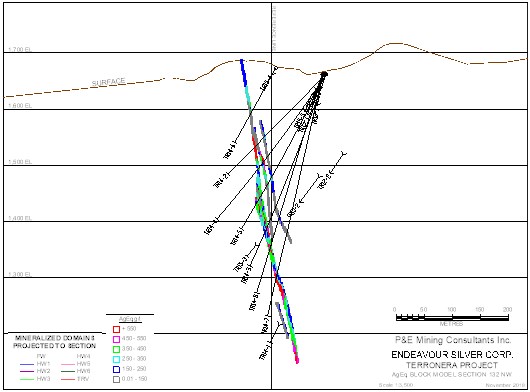
Figure 14-20 Silver Equivalent Block Model Section 132 NW, Terronera Deposit
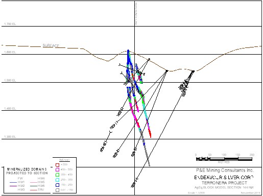
Figure 14-21 Silver Equivalent Block Model Section 144 NW, Terronera Deposit
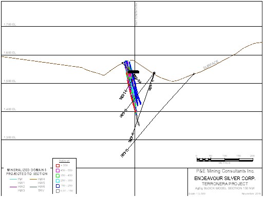
Figure 14-22 Silver Equivalent Block Model Section 150 NW, Terronera Deposit
The coordinate system for the plans shown below is WGS 84 / UTM Zone 13Q.
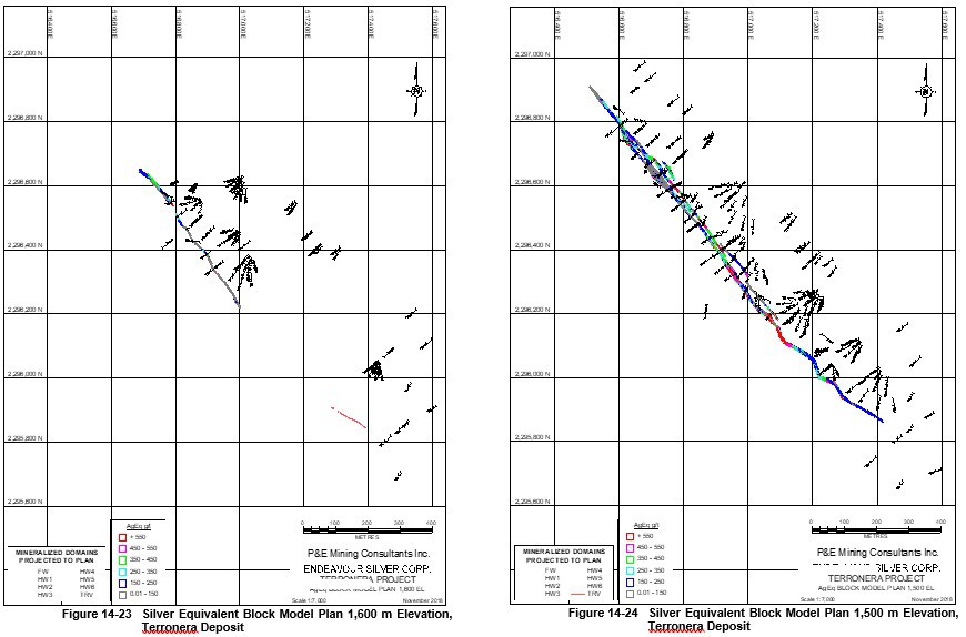
14.1.15.2 Classification Block Model Cross Sections and Plans, Terronera Deposit
Selected vertical cross-sections and plans of the AgEq grade blocks are presented below. The coordinate system for the plans is WGS 84 / UTM Zone 13Q.
Figure 14-27 Classification Block Model Vertical Cross Section 108 NW, Terronera Deposit
Figure 14-28 Classification Block Model Vertical Cross Section 120 NW, Terronera Deposit
Figure 14-29 Classification Block Model Vertical Cross Section 132 NW, Terronera Deposit
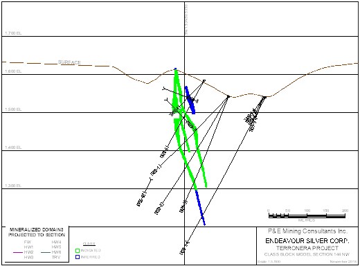
Figure 14-30 Classification Block Model Vertical Cross Section 144 NW, Terronera Deposit
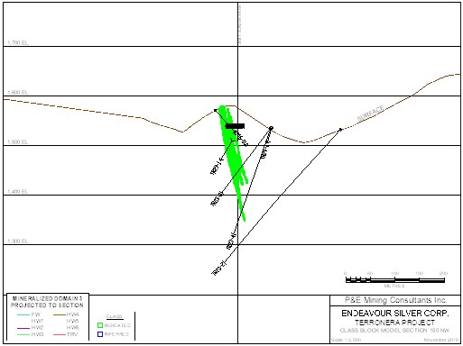
Figure 14-31 Classification Block Model Vertical Cross Section 150 NW, Terronera Deposit
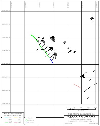 | 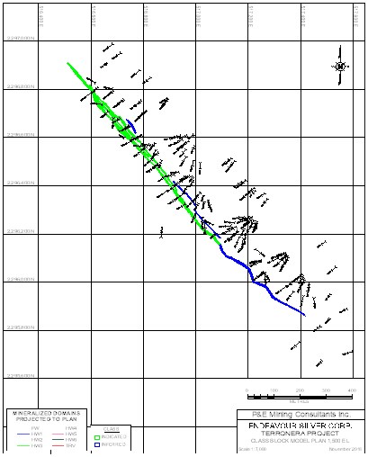 |
| Figure 14-32 Classification Block Model Plan 1,600 m Elevation, Terronera Deposit | Figure 14-33 Classification Block Model Plan 1,500 m Elevation, Terronera Deposit |
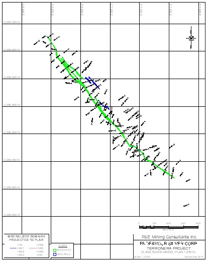 | 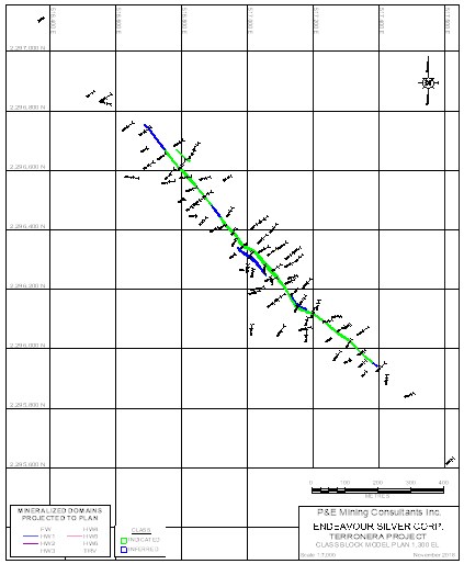 |
| Figure 14-34 Classification Block Model Plan 1,400 m Elevation, Terronera Deposit | Figure 14-35 Classification Block Model Plan 1,300 m Elevation, Terronera Deposit |
14.2 La Luz Deposit Mineral Resource Estimate
14.2.1 Introduction
This section summarizes the Mineral Resource estimate on the La Luz Deposit. The Mineral Resource estimate presented herein is reported in accordance with the Canadian Securities Administrators’ National Instrument 43-101 and has been estimated in conformity with generally accepted CIM « Estimation of Mineral Resources and Mineral Reserves Best Practices » guidelines. Mineral Resources are not Mineral Reserves and do not have demonstrated economic viability. There is no guarantee that all or any part of the Mineral Resource will be converted into Mineral Reserve. Confidence in the estimate of Inferred Mineral Resources is insufficient to allow the meaningful application of technical and economic parameters or to enable an evaluation of economic viability worthy of public disclosure. Mineral Resources may be affected by further infill and exploration drilling that may result in increases or decreases in subsequent Mineral Resource estimates.
This Mineral Resource estimate was undertaken by Yungang Wu, P.Geo., and Eugene Puritch, P.Eng., FEC, CET of P&E Mining Consultants Inc., Brampton, Ontario, both independent Qualified Persons in terms of NI43-101, from information and data supplied by Endeavour Silver. The effective date of this Mineral Resource estimate is August 7, 2018.
14.2.2 Data Verification
P&E carried out data verification for silver and gold assays contained in the Mineral Resource wireframes against laboratory certificates that were obtained directly from ALS Chemex laboratory in Hermosillo, Mexico. No errors were found.
A total 46 raw Ag and Au assays were adjusted for core recovery, of which 4 assays used for the Mineral Resource estimate. If the core recovery was 92%, for example, Ag and Au assay values were reduced to 92% of the original analytical value. The adjusted values are recorded in the database as « Ag_REC » and « Au_REC » and these values were used for the Mineral Resource estimate. P&E’s site visit confirmed that core recovery was generally very good, the vein was very competent, and recovery was over 90% for the core examined. The oxidation level was generally low, and the mineralization appeared unleached. P&E agrees with Endeavour Silver that the use of « recoverable » grades is a conservative approach.
In addition to the data verification reported above, P&E reviewed the QAQC for the Terronera Project analyses and concludes that the analyses are acceptable. In P&E’s opinion the drill hole and assay/analytical databases may be used for the estimation of Mineral Resources.
14.2.3 Database
All drilling and assay data were provided in the form of Excel data files by Endeavour Silver. The Gems database for this Mineral Resource estimate, constructed by P&E, consisted of 41 diamond drill holes, totalling 9,795.65 m, completed in 2016 and 2017. A drill hole plan is shown in Figure 14-36.
The database assay table contained a total of 1,472 samples that were analyzed for Au, Ag and 34 other elements. The Au and Ag assays were factored downward by core recovery and marked as Au_REC and Ag_REC in the database which was utilized for the Mineral Resource estimate.
All drill hole survey and assay values are expressed in metric units, while grid coordinates are in the WGS84, Zone 13Q UTM geodetic reference system.
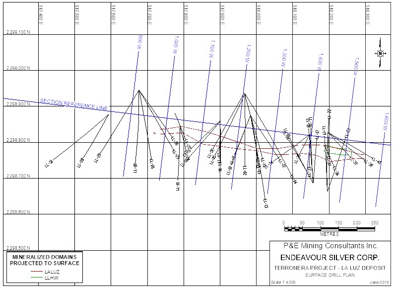
Coordinate system: WGS 84 / UTM Zone 13Q
Figure 14-36 La Luz Surface Drill Hole Plan
14.2.4 Domain Interpretation
Two mineralized veins were generated during the course of this Mineral Resource estimate. A cut-off grade of 150 g/t silver equivalence (AgEq) was applied to the wireframes. The AgEq was calculated with a formula of AgEq = Ag + (Au x 75). The wireframes were created from successive polylines on west facing vertical cross-sections with 50 m spacing. In some cases, mineralization below the above mentioned 150 g/t AgEq cut-offs was included for the purpose of maintaining zonal continuity. On each cross-section, polyline interpretations were digitized from drill hole to drill hole but not typically extended more than 25 meters into untested territory. Minimum constrained sample length for interpretation was 0.9 m.
A topographic surface was provided by Endeavour Silver.
The resulting domains were used as hard boundaries during Mineral Resource Estimation, for rock coding, statistical analysis and compositing limits. The 3-D domains are presented in Figure 14-17
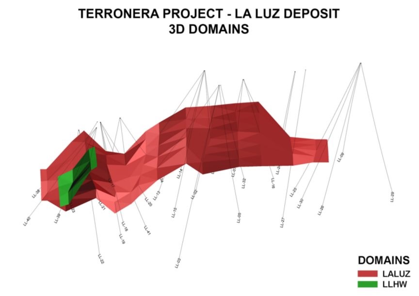
Coordinate system: WGS 84 / UTM Zone 13Q
Figure 14-37 La Luz Deposit 3-D Domains and Wireframes
14.2.5 Model Rock Code Determination
A unique model code was assigned for each mineralized domain in the Mineral Resource model. The codes applied for the models are tabulated in Table 14-14.
Table 14-14 La Luz Model Rock Code Description and Volume
Domains | Rock Type | Volume (m3) |
La Luz Vein | 1,000 | 71,601 |
La Luz HW | 2,000 | 4,132 |
Air | 0 |
|
Waste | 99 |
|
Note: HW = Hanging Wall
14.2.6 Compositing
The basic statistics of all constrained assays and sample length are shown in Table 14-15.
Table 14-15 Basic Statistics of All Constrained Assays and Sample Length
Variable | Ag | Au | Length (m) |
Number of Samples | 96.00 | 96.00 | 96.00 |
Minimum Value (g/t) | 0.90 | 0.01 | 0.15 |
Maximum Value (g/t) | 2,600.00 | 320.00 | 1.50 |
Mean (g/t) | 180.82 | 15.99 | 0.58 |
Median (g/t) | 37.25 | 4.67 | 0.55 |
Variance | 150,234.16 | 1,835.74 | 0.07 |
Standard Deviation (g/t) | 387.60 | 42.85 | 0.26 |
Coefficient of Variation | 2.14 | 2.68 | 0.45 |
Approximately 98% of the constrained sample lengths were 1 m or less, with an overall average of 0.58 m. In order to regularize the assay sampling intervals for grade interpolation, a 1.0 m compositing length was selected for the drill hole intervals that fell within the constraints of the above-mentioned domains. The composites were calculated for Ag and Au over 1.0 m lengths starting at the first point of intersection between assay data hole and hanging wall of the 3-D zonal constraint. The compositing process was halted upon exit from the footwall of the aforementioned constraint. Un-assayed intervals and below detection limit assays were set to 0.001 g/t for both Au and Ag. Any composites that were less than 0.25 m in length were discarded so as not to introduce any short sample bias in the interpolation process. The constrained composite data were extracted to point files for a capping study. The composite statistics are summarized in Table 14-16.
Table 14-16 Composite Summary Statistics
Variable | Ag Composite | Au Composite | Ag Capped Composite | Au Capped Composite |
Number of Samples | 63 | 63 | 63 | 63 |
Minimum Value (g/t) | 1.15 | 0.01 | 1.15 | 0.01 |
Maximum Value (g/t) | 1,510.63 | 168.73 | 1,000.00 | 90.00 |
Mean (g/t) | 154.96 | 13.58 | 146.85 | 12.33 |
Median (g/t) | 45.80 | 5.48 | 45.80 | 5.48 |
Geometric Mean (g/t) | 50.35 | 3.27 | 50.02 | 3.24 |
Variance | 66,346.86 | 645.10 | 48,443.70 | 354.18 |
Standard Deviation (g/t) | 257.58 | 25.40 | 220.10 | 18.82 |
Coefficient of Variation | 1.66 | 1.87 | 1.50 | 1.53 |
14.2.7 Grade Capping
Grade capping was investigated on the 1.0 m composite values in the database within the constraining domains to ensure that the possible influence of erratic high values did not bias the database. Ag and Au composite Log-normal histograms were generated for each mineralized domain and the resulting graphs are exhibited in Figure 14-38 and Figure 14-39 The Ag and Au grade capping values are detailed in Table 14-17. The capped composites were utilized to develop variograms and for block model grade interpolation.
Figure 14-38 La Luz Ag Composite Distribution
Figure 14-39 La Luz Au Composite Distribution
Table 14-17 Grade Capping Values
Element | Total No. of Comps | Cap Value (g/t) | No. of Capped Comps | Mean | Coefficient of Variation | Capping Percent | ||
Comps | Capped Comps | Comps | Capped Comps |
| ||||
Au | 63 | 90 | 1 | 13.58 | 12.33 | 1.87 | 1.53 | 98.4% |
Ag | 63 | 1,000 | 1 | 154.96 | 146.85 | 1.66 | 1.50 | 98.4% |
Note: Comps =composite, Cap = capped, No. = number
14.2.8 Semi-Variography
A semi-variography study was performed as a guide to determining a grade interpolation search strategy. Omni, along strike, down dip and across dip semi-variograms were attempted using Ag and Au capped composites. Selected variograms are attached in Figure 14-40 to Figure 14-45.
Continuity ellipses based on the observed ranges were subsequently generated and utilized as the basis for estimation search ranges, distance weighting calculations and Mineral Resource classification criteria. Anisotropy was modeled based on an average strike direction of 97°, -75° north-northeast down dip.
Figure 14-40 La Luz Ag Omnivariogram
Figure 14-41 La Luz Ag Along Strike Variogram
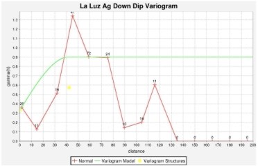
Figure 14-42 La Luz Ag Down Dip Variogram
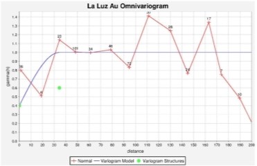
Figure 14-43 La Luz Au Omnivariogram
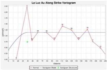
Figure 14-44 La Luz Au Along Strike Variogram
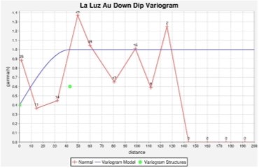
Figure 14-45 La Luz Au Down Dip Variogram
14.2.9 Bulk Density
424 bulk density measurements from 37 drill holes were provided by Endeavour Silver, of which 79 measurements were constrained within the mineralized veins with an average bulk density of 2.65 t/m3. Bulk density determination by Endeavour Silver was undertaken with water displacement on waxed drill core.
David Burga, P.Geo of P&E collected 12 samples in Jan 2018 during his site visit. The samples were tested in AGAT Laboratories in Mississauga, with an average bulk density of 2.62 t/m3.
14.2.10 Block Modelling
The La Luz Mineral Resource block model was constructed using Geovia Gems V6.8 modelling software and the block model origin and block size are tabulated in Table 14-18. The block model consists of separate models for estimated grade, rock type, volume percent, bulk density and classification attributes.
Table 14-18 La Luz Block Model Definition
Direction | Origin | No. of Blocks | Block Size (m) |
X | 517,699.391 | 306 | 2 |
Y | 2,298,795.037 | 186 | 0.5 |
Z | 1,392 | 190 | 2 |
Rotation |
| 7° clockwise |
|
All blocks in the rock type block model were initially assigned a waste rock code of 99, corresponding to the surrounding country rocks. All mineralized domains were used to code all blocks within the rock type block model that contain 1% or greater volume within the domains. These blocks were assigned their appropriate individual rock codes as indicated in Table 14-14. The topographic surfaces were subsequently utilized to assign rock code 0 for air, to all blocks 50% or greater above the surface.
A volume percent block model was set up to accurately represent the volume and subsequent tonnage that was occupied by each block inside the constraining domains. As a result, the domain boundary was properly represented by the percent model ability to measure individual infinitely variable block inclusion percentages within that domain. The minimum percentage of the mineralized block was set to 1%.
The bulk density of each mineralized domain was interpolated with the NN method using 79 bulk density measurements.
The Ag and Au grade were interpolated with Inverse Distance Cubed (1/D3) using capped composites. Multiple passes were executed for the grade interpolation to progressively capture the sample points in order to avoid over smoothing and preserve local grade variability. Search ranges were based on the variograms and search directions which were aligned with the strike and dip directions of each mineralized domain accordingly. Grade blocks were interpolated using the parameters in Table 14-19.
Table 14-19 Gold and Silver Block Model Interpolation Parameters
Element | Pass | Dip Range (m) | Strike Range (m) | Across Dip Range (m) | Max. No. of Samples per Hole | Min. No. of Samples | Max. No. of Samples |
Ag | I | 45 | 45 | 10 | 2 | 3 | 12 |
II | 90 | 90 | 20 | 2 | 1 | 12 | |
Au | I | 40 | 40 | 10 | 2 | 3 | 12 |
II | 80 | 80 | 20 | 2 | 1 | 12 |
Selected cross-sections and plans of the Ag grade blocks are presented in section 14.2.15.1.
The Ag equivalence (AgEq) were manipulated using formula:
AgEq g/t = Ag g/t + (Au g/t * 75).
14.2.11 Mineral Resource Classification
In P&E’s opinion, the drilling, assaying and exploration work of the La Luz Deposit supporting this Mineral Resource estimate are sufficient to indicate a reasonable potential for economic extraction and thus qualify it as a Mineral Resource under the CIM definition standards. The Mineral Resources were classified as Indicated and Inferred based on the geological interpretation, semi-variogram performance and drill hole spacing. The Indicated Mineral Resources were classified for the blocks interpolated by the grade interpolation Pass I in the
Table 14-19, which used at least three composites from a minimum of two holes; and Inferred Mineral Resources were classified for all remaining grade populated blocks with Pass II within the mineralized domains. The classifications have been adjusted on long section to reasonably reflect the distribution of each classification. Selected classification block cross-sections and plans are attached in section 14.2.15.2.
14.2.12 Mineral Resource Estimate Cut-off
The Mineral Resource estimate was derived from applying a AgEq cut-off grade to the block model and reporting the resulting tonnes and grade for potentially mineable areas. Table 14-20 shows the rationale supporting the AgEq cut-off grade that determines the underground potentially economic portions of the constrained mineralization.
Table 14-20 La Luz Underground AgEq Cut-Off Grade Calculation
| Comments |
Au Price | $1,275/oz based on approx. two-year average at June 30/18 |
Ag Price | $17/oz based on approx. two-year average at June 30/18 |
AgEq Recovery | 87% |
Mining Cost | $40/tonne mined |
Process Cost | $23/tonne mined |
General & Administration | $8/tonne mined |
AgEq Refining $/oz | $0.5 |
AgEq Smelter Payable | 99% |
Therefore, the AgEq cut-off grade for the underground Mineral Resource estimate is calculated as follows:
Mining, Processing and G&A costs per ore tonne = ($40 + $23 + $8) = $71/tonne
[($71)/[($17.00 – 0.50)/31.1035 x 87% Recovery x 99% Payable] = 155.4 g/t, Use 150 g/t
14.2.13 La Luz Mineral Resource Estimate
P&E considers that the silver and gold mineralization of La Luz Deposit is potentially amenable to underground extraction. The resulting Mineral Resource estimate is tabulated in the Table 14-21.
Table 14-21 La Luz Mineral Resource Estimate at a Cut-off Grade of 150 g/t AgEq (1-5)
Classification | Tonnage (kt) | Ag (g/t) | Contained Ag (koz) | Au (g/t) | Contained Au (koz) | AgEq (g/t) | Contained AgEq (koz) |
Indicated | 126 | 192 | 779 | 13.60 | 55 | 1,212 | 4,904 |
Inferred | 58 | 145 | 269 | 12.15 | 23 | 1,060 | 1,994 |
1. Mineral Resources, which are not Mineral Reserves do not have demonstrated economic viability. The estimate of Mineral Resources may be materially affected by environmental, permitting, legal, title, taxation, socio-political, marketing, or other relevant issues.
2. The Inferred Mineral Resource in this estimate has a lower level of confidence than that applied to an Indicated Mineral Resource and must not be converted to a Mineral Reserve. It is reasonably expected that the majority of the Inferred Mineral Resource could be upgraded to an Indicated Mineral Resource with continued exploration.
3. The Mineral Resources in this report were estimated using the Canadian Institute of Mining, Metallurgy and Petroleum (CIM), CIM Standards on Mineral Resources and Reserves, Definitions and Guidelines prepared by the CIM Standing Committee on Reserve Definitions and adopted by the CIM Council.
4. AgEq g/t = Ag g/t + (Au g/t x 75).
Mineral Resources are sensitive to the selection of a reporting AgEq cut-off grade as demonstrated in Table 14-22.
Table 14-22 La Luz Sensitivity of Mineral Resource Estimate to AgEq Cut-off
Classification | Cut-off AgEq (g/t) | Tonnage (kt) | Ag (g/t) | Contained Ag (koz) | Au (g/t) | Contained Au (koz) | AgEq (g/t) | Contained AgEq (koz) |
Indicated | 1,000 | 51 | 311 | 512 | 26.45 | 43 | 2,295 | 3,737 |
750 | 59 | 283 | 542 | 24.25 | 46 | 2,102 | 3,992 | |
500 | 75 | 243 | 582 | 20.85 | 50 | 1,807 | 4,332 | |
250 | 117 | 202 | 756 | 14.58 | 55 | 1,296 | 4,881 | |
225 | 120 | 198 | 766 | 14.19 | 55 | 1,262 | 4,891 | |
200 | 123 | 196 | 772 | 13.96 | 55 | 1,243 | 4,897 | |
190 | 123 | 195 | 773 | 13.88 | 55 | 1,236 | 4,898 | |
180 | 124 | 194 | 775 | 13.80 | 55 | 1,229 | 4,900 | |
170 | 125 | 193 | 777 | 13.72 | 55 | 1,222 | 4,902 | |
160 | 126 | 193 | 778 | 13.66 | 55 | 1,218 | 4,903 | |
150 | 126 | 192 | 779 | 13.60 | 55 | 1,212 | 4,904 | |
140 | 127 | 191 | 781 | 13.54 | 55 | 1,207 | 4,906 | |
130 | 128 | 191 | 782 | 13.47 | 55 | 1,201 | 4,907 | |
120 | 128 | 190 | 783 | 13.40 | 55 | 1,195 | 4,908 | |
110 | 129 | 189 | 785 | 13.33 | 55 | 1,189 | 4,910 | |
100 | 130 | 188 | 786 | 13.23 | 55 | 1,180 | 4,911 | |
50 | 134 | 183 | 792 | 12.82 | 55 | 1,145 | 4,917 | |
0.01 | 137 | 180 | 793 | 12.57 | 55 | 1,123 | 4,918 |
Classification | Cut-off AgEq (g/t) | Tonnage (kt) | Ag (g/t) | Contained Ag (koz) | Au (g/t) | Contained Au (koz) | AgEq (g/t) | Contained AgEq (koz) |
Inferred | 1,000 | 21 | 146 | 99 | 25.87 | 18 | 2,086 | 1,449 |
750 | 26 | 130 | 109 | 23.13 | 19 | 1,865 | 1,534 | |
500 | 29 | 131 | 122 | 21.42 | 20 | 1,738 | 1,622 | |
250 | 52 | 154 | 256 | 13.35 | 22 | 1,155 | 1,906 | |
225 | 53 | 151 | 259 | 12.99 | 22 | 1,125 | 1,909 | |
200 | 55 | 148 | 262 | 12.67 | 22 | 1,098 | 1,912 | |
190 | 55 | 148 | 263 | 12.59 | 22 | 1,092 | 1,913 | |
180 | 56 | 147 | 265 | 12.49 | 22 | 1,084 | 1,915 | |
170 | 56 | 147 | 266 | 12.37 | 22 | 1,075 | 1,916 | |
160 | 57 | 146 | 267 | 12.26 | 22 | 1,066 | 1,917 | |
150 | 58 | 145 | 269 | 12.15 | 23 | 1,060 | 1,994 | |
140 | 59 | 144 | 271 | 11.98 | 23 | 1,043 | 1,996 | |
130 | 59 | 143 | 272 | 11.85 | 23 | 1,032 | 1,997 | |
120 | 60 | 142 | 273 | 11.76 | 23 | 1,024 | 1,998 | |
110 | 60 | 142 | 274 | 11.69 | 23 | 1,019 | 1,999 | |
100 | 61 | 141 | 274 | 11.62 | 23 | 1,013 | 1,999 | |
50 | 62 | 138 | 276 | 11.37 | 23 | 991 | 2,001 | |
0.01 | 63 | 137 | 279 | 11.21 | 23 | 978 | 2,004 |
14.2.14 Confirmation of Estimate
The block model was validated using several industry standard methods including visual and statistical methods. Visual examination of composite and block grades on successive plans and sections on-screen to confirm that the block model correctly reflects the distribution of sample grades.
Review of estimation parameters include:
• Number of composites used for estimation
• Number of holes used for estimation
• Mean Distance to sample used
• Number of passes used to estimate grade
• Mean value of the composites used.
A comparison of Ag and Au mean grades of composites with block model is presenting in Table 14-23.
Table 14-23 Average Grade Comparison of Composites with Block Model
Data Type | Ag (g/t) | Au (g/t) |
Composites | 155 | 13.58 |
Capped Composites | 147 | 12.33 |
Block Model ID3* | 169 | 12.21 |
Block Model NN** | 171 | 12.14 |
* block model grade interpolated using Inverse Distance Cubed.
** block model grade interpolated using Nearest Neighbour.
The comparison above shows the average grades of the Au blocks in the block models to be slightly lower while Ag grade higher than the average grades of capped composites used for grade estimation. This is probably due to the localized clustering were smoothed by the block modeling grade interpolation process. The block model grade will be more representative than the capped composites due to the block model’s 3-D spatial distribution characteristics.
A volumetric comparison was performed with the block model volume versus the geometric calculated volume of the domain solids and the differences are detailed in Table 14-24.
Table 14-24 Volumetric Comparison of Block Model with Geometric Wireframes
Geometric Volume of Wireframes | 75,733 m3 |
Block Model Volume | 75,701 m3 |
Difference % | 0.04% |
Ag and Au local trends were evaluated by comparing the ID3 and NN estimate against their Composites and Capped Composites. As shown in Figure 14-46 through Figure-51, both the Ag and Au grade interpolation with Inverse Distance Cubed and Nearest Neighbour agreed well.
Figure 14-46 La Luz Silver Grade Swath Easting Plot
Figure 14-47 Silver Grade Swath Northing Plot
Figure 14-48 Silver Grade Swath Elevation Plot
Figure 14-49 Gold Grade Swath Easting Plot
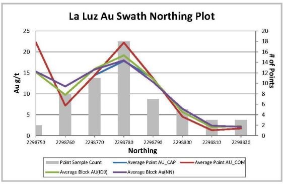
Figure 14-50 Gold Grade Swath Northing Plot
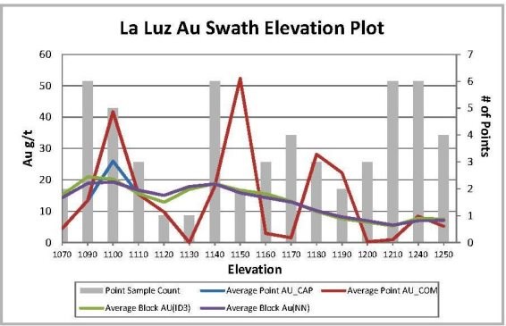
Figure 14-51 Gold Grade Swath Elevation Plot
A comparison of the grade-tonnage curve of the Ag and Au grade model interpolated with Inverse Distance cubed (1/d3) and Nearest Neighbour (NN) on a global mineralization basis are presented in Figure 14-52 and Figure 14-53 for Ag and Au respectively.
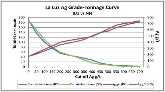
Figure 14-52 Silver Grade and Tonnage Comparisons for ID3 and NN Interpolation
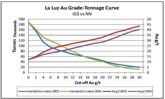
Figure 14-53 Gold Grade and Tonnage Comparisons for ID3 and NN Interpolation
14.2.15 Figures and Maps Pertaining to the Mineral Resource Estimate for the La Luz Deposit
To visually understand the La Luz deposit Mineral Resource Estimate, figures, vertical cross sections and plans are included below. The AgEq block model is represented in Figure 14 54 to Figure 14 59 and the classification block model is shown in Figure 14 60 to Figure 14 65. The surface plan drill hole location map is shown in Figure 14 36 and the La Luz Mineral Resource 3-D domains and wireframes are shown in Figure 14 37. The log normal histograms, Figure 14 38 and Figure 14 39, and variograms, Figure 14 40 to Figure 14 45 are shown in sections above.
14.2.15.1 AgEq Block Model Vertical Cross Sections and Plans
Selected cross-sections and plans of the Ag grade blocks are presented in below. The coordinate system for the plans is WGS 84 / UTM Zone 13Q.
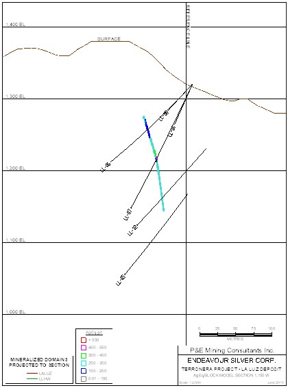
Figure 14-54 Silver Equivalent Block Model Section 1,150 W, La Luz Deposit
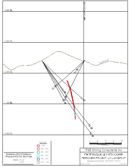 | 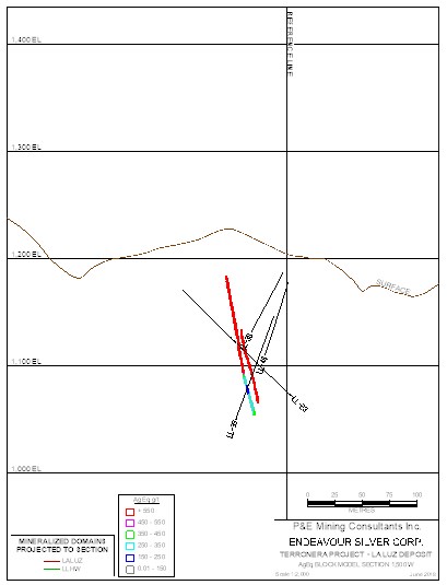 |
| Figure 14-55 Silver Equivalent Block Model Section 1,400 W, La Luz Deposit | Figure 14-56 Silver Equivalent Block Model Section 1,500 W, La Luz Deposit |
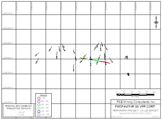
Figure 14-57 Silver Equivalent Block Model Plan 1,250 m Elevation, La Luz Deposit
Figure 14-58 Silver Equivalent Block Model Plan 1,150 m Elevation, La Luz Deposit
Figure 14-59 Silver Equivalent Block Model Plan 1,100 m Elevation, La Luz Deposit
14.2.15.2 Classification Block Model Cross Sections and Plans
Selected classification block cross-sections and plans are shown below. The coordinate system for the plans is WGS 84 / UTM Zone 13Q.
 |  |
| Figure 14-60 Classification Block Model Vertical Cross Section 1,150 W, La Luz Deposit | Figure 14-61 Classification Block Model Vertical Cross Section 1,400 W, La Luz Deposit |
Figure 14-62 Classification Block Model Vertical Cross Section 1,500 W, La Luz Deposit
Figure 14-63 Classification Block Model Plan 1,250 m Elevation, La Luz Deposit
Figure 14-64 Classification Block Model Plan 1,150 m Elevation, La Luz Deposit
Figure 14-65 Classification Block Model Plan 1,050 m Elevation, La Luz Deposit
15 Mineral Reserve Estimates
The deposits are planned to be mined by a combination of underground mining methods:
• Terronera: mechanized cut-and-fill (MCF) and longhole retreat mining (LH)
• La Luz: Longhole retreat mining (LH) and resue cut-and-fill resue mining (CFR).
15.1 Cut-Off Grade
Both gold and silver are payable elements for the Terronera and La Luz deposits. Due to the differences in size between the two deposits as well as orebody geometry and silver and gold grades, cut-off grades for each deposit by mining method have been developed. Cut-off-grades have been calculated (using AgEq) to reflect the dominant payable element across the combined project. The AgEq formula is:
AgEq = (77.94 * Au) + Ag.
Cut-off grades for the two deposits are shown in Table 15-2 and reflect the input parameters shown in Table 15-1.
Table 15-1 Cut-Off Grade Input Parameters
Parameter | Unit | Value for Gold | Value for Silver |
Metal Price | US$ / oz | 1,325 | 17.00 |
Recovery | % | 79.8 | 84.9 |
Mass Pull | % | 2.2 | |
Concentrate Payable | % | 98.0 | 97.5 |
Refining Cost | US$ / oz | 6.00 | |
Tailings Cost | USS$ / dmt | 110.00 | |
Transport Cost | US$ / dmt | 37.06 | |
Sales Cost | US$ / dmt | 5.00 | |
Transport Losses | % | 0.2 | |
Property NSR Royalty | % | 2.00 | |
Government Precious Metals Royalty | % | 0.5 | |
Arsenic Penalty* | US$ / dmt | 6.00 | |
Concentrate Costs | US$ / dmt | 3.48 | |
Payable Recovery | % | 82.45 | 81.2 |
* Arsenic penalty is $2.00 per 0.1% above 0.2%
** Antimony penalty is $0.50 per 0.01% above 0.05%
*** Bismuth penalty is $0.30 per 0.01% above 0.04%.
Table 15-2 Cut-Off Grade Calculations
Item | Terronera | Common | La Luz | |
Cost | LH | MCF | Dev | CFR |
Mining | 30.00 | 49.00 | 20.00 | 51.00 |
Processing | 28.46 | 28.46 | 28.46 | 28.46 |
G&A | 8.49 | 8.49 | 8.49 | 8.49 |
Total: | 66.95 | 85.95 | 56.95 | 87.95 |
Recovery Ag (%): | 84.9 | 84.9 | 84.9 | 84.9 |
Payable (%): | 82.5 | 82.5 | 82.5 | 82.5 |
Calculated COG (AgEq g/t): | 174.99 | 224.65 | 148.85 | 229.88 |
Assumed COG (AgEq g/t): | 175.00 | 225.00 | 150.00 | 230.00 |
Dev = Development
COG = cut-off grade
15.2 Mining Dilution
Some waste material will be mined. Two types of dilution were applied to the stope designs:
• External wall dilution – waste that falls into the stope from outside the geometry of the stope shape
• Fill dilution – backfill expected to fall into the stope being mined from adjacent stopes and/or inadvertently scraped off the stope floors during mucking.
The dilution modes were estimated by mining method and stope type, based on the stope design tonnages, and are summarized in Table 15-3.
Table 15-3 Dilution by Mining Method
Mine | Mining Method | Wall Dilution % | Fill Dilution % |
Terronera | MCF | 11 | 2 |
LH | 30 | 4 | |
La Luz | CFR | 20 | 2 |
LH | 36 | 4 |
External dilution waste grades adjacent to the planned stopes were calculated from separate waste hanging wall and waste foot wall block models. The foot wall and hanging wall block models were calculated as separate domains from drill hole assay composites located inside a 2 m envelope extending beyond the Mineral Resource wireframes. The same estimation parameters were used for the Mineral Reserve estimates as were used in Mineral Resource estimate.
The classification of Indicated or Inferred for the waste blocks was assigned from the classification of the adjacent Mineral Resource blocks, to ensure that the classification was consistent between the waste and mineralized domains. The hanging wall and foot wall waste dilution grades were calculated for each individual stope from the adjacent hanging wall and foot wall blocks extending into the 2 m wireframe envelope. Any inferred blocks were assigned zero waste grade. The individual stope dilution grade was applied to the designed external dilution tonnes and combined with the Mineral Resource tonnes and grades for the final stope grade. Fill dilution was assumed to carry zero metal grades.
Additional sources of dilution are planned or internal dilution and dilution from Inferred Mineral Resources. Planned dilution comprises material that may be below the cut-off grade for each specific mining method and that is unavoidable in the stope design shape. Planned dilution carries the metal grades of the assigned blocks within the stope shape. Any Inferred Mineral Resources within the Mineral Reserve stope shapes were treated as waste and assigned zero metal grades.
15.3 Mining Recovery
Extraction for the LH method is largely dependent on the accuracy of longhole drilling and explosives detonation over the length of the drill holes (20 m and 16 m drill, respectively for the Terronera and La Luz deposits) that will be required to properly break the ore. Where holes deviate from the stope limits, some material will remain hung up and may never report to the stope floor for recovery.
Lesser factors considered to affect mining recoveries in LH mining include ragged mucking floors and limited visibility for remote mucking, both of which will result in ore left behind in the stope.
A mining recovery of 95% was assigned to the LH method based on industry norms as well as Moose Mountain’s operational experience with remote mucking of stopes of similar size and dip.
Recovery for MCF, CFR, and ore sublevel drift development typically results in higher recoveries than can be obtained using bulk mining methods. A mining recovery of 98% of the material blasted has been assumed for MCF and CFR mining ,and 100% is assumed for ore sublevel development.
15.4 Mineral Reserve Table
The Probable Mineral Reserve estimates for the Terronera and La Luz deposits are provided in Table 15-4. There is no Proven Mineral Reserve for either deposit.
Table 15-4 Terronera and La Luz Probable Mineral Reserve(1-5)
Deposit | Tonnes (kt) | Au (g/t) | Ag (g/t) | AgEq (g/t) | Au (koz) | Ag (koz) | AgEq (koz) |
Terronera | 5,356 | 2.08 | 205 | 367 | 358 | 35,268 | 63,160 |
La Luz | 207 | 7.87 | 112 | 725 | 52 | 745 | 4,828 |
Combined | 5,563 | 2,29 | 201 | 380 | 410 | 36,013 | 67,988 |
1. The Qualified Person for the estimate is Michael Petrina, P.Eng., who is an employee of Moose Mountain Technical Services. Mineral Reserves have an effective date of March 23, 2020.
2. Mineral Reserves are reported using the 2014 CIM Definition Standards.
3. Mineral Reserves are reported using a silver equivalency (AgEq) cut-off formula AgEq g/t = Ag g/t + (Au g/t x 77.94). Depending on mining method the AgEq cut-off can range from 175 g/t AgEq to 230 g/t AgEq. Inputs to the AgEq determination included: metal prices of US$1,325/oz Au, and US$17.00/oz Ag; metallurgical recovery of 79.8% for gold and 84.9% for silver; payability in concentrate of 98.0% for gold and 97.5% for silver; consideration of refining (US$6/oz), tailings (US$110.00/dmt), transport (US$37.06/dmt), sales (US$5.00/dmt), and concentrate (US$3.48/dmt) costs; transport losses (0.2%), royalties (2% NSR and 0.5% Government); and As penalties payable in the concentrate of US$6.00/dmt. Historically mined areas were depleted from the Terronera wireframe.
15.5 Factors That May Affect the Mineral Reserve Estimate
Factors that could affect the Mineral Reserve estimate include, but are not limited to: dilution; metal prices; site operating costs and mining recoveries; and management of the operation and its environmental impacts.
The factor with the largest impact on the Mineral Reserve estimate is metal prices, with the Terronera deposit being influenced by both gold and silver prices, and La Luz deposit being most heavily influenced by gold prices. When both deposits are combined in the LOM plan, the price of gold and silver will have the greatest impact on the Mineral Reserve estimate.
There are no mining, metallurgical, infrastructure or other relevant factors that may materially affect the Mineral Reserve estimates.
16.1 Introduction
The proposed underground operations at the Terronera and La Luz mines will be accessed via ramps. In the case of the Terronera mine, the ramp accesses will connect to the deposit via:
• A main haulage drift from the north with the portal approximately 200 m from the mill. The ramp will access the deposit at the 1,250 m level near the western end of the deposit M1 (see Figure 16-1)
• The west ramp with portal location at the 1,480m elevation for early access to the western (bottom of the upper M7 block (see Figure 16-1) portion of the deposit, as well as early access to the 1,380 m elevation footwall access drift
• The M9 ramp, located at the 1,527 m elevation for early access to the central and eastern portions of the deposit.
Ore from both the Terronera and La Luz deposits will be transported via 30-t low-profile haul truck to surface. Terronera will have a truck haulage way for transporting ore from underground directly to a stockpile in front of the process plant area, whereas all material from La Luz deposit is envisioned to be hauled entirely by contractor truck to the same stockpile area.
Terronera will use MCF mining as its primary mining method and longhole retreat as the secondary method whilst La Luz will be mined primarily using longhole retreat mining and resue cut and fill mining as the secondary mining method.
Both deposits will use backfill comprising either cemented or non-cemented rock fill or later in the mine life, cemented or non-cemented quarry rock fill. Cement contents will vary from 4 to 8% by mass as required.
Development of both deposits will begin at the same time, the first day of month 8 of Year -3. Until the Terronera process plant is complete at the end of Year -1, Month 12, ore from the La Luz deposit will mined as quickly as possible, placed on a surface stockpile and loaded into a surface haul truck and trucked approximately 600 kms to Endeavour Silver’s Bolañitos process plant for processing , whilst the Terronera mill is being brought into production.
Production from La Luz will average roughly 240 tpd over its life, with the Terronera deposit’s production ramping up to 1,600 tpd across the year spanning Year 1, Month 7 through to Year 3, Month 1. Production will remain at a total 1,600 tpd across both deposits until Year 9, Month 10, when it will gradually decline to about 1,270 tpd by the end of Year 10, and the end of the mine life.

Source: Moose Mountain, June 2020
Figure 16-1 Terronera Deposit Longitudinal Projection
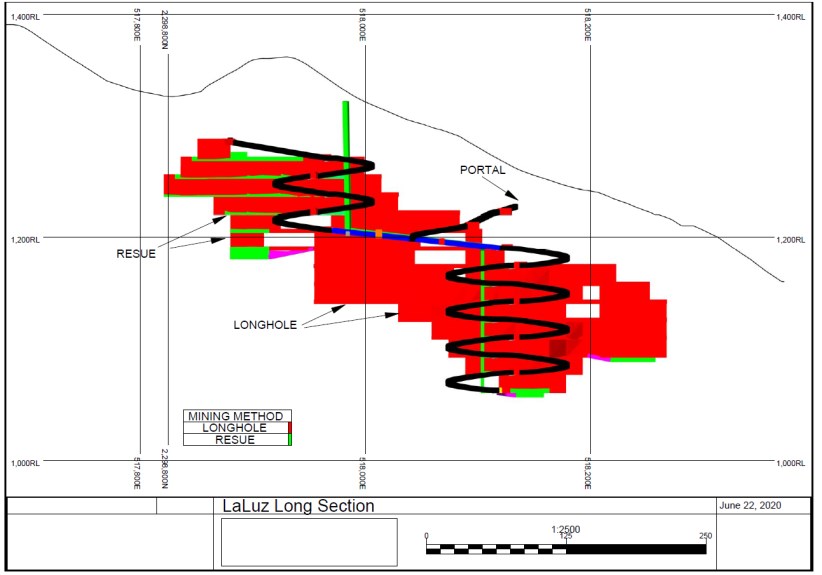
Source : Moose Mountain, June 2020
Figure 16-2 La Luz Deposit Longitudinal Projection
The Terronera deposit comprises several veins of varying thicknesses, whereas the La Luz deposit consists of a single narrow vein. Mechanized cut and fill and longhole retreat mining will be used for production at the Terronera deposit, and longhole retreat and resue cut and fill mining will be used for production at La Luz deposit (Figure 16-2).
The plan view for both Terronera and La Luz deposits is shown in Figure 16-3.
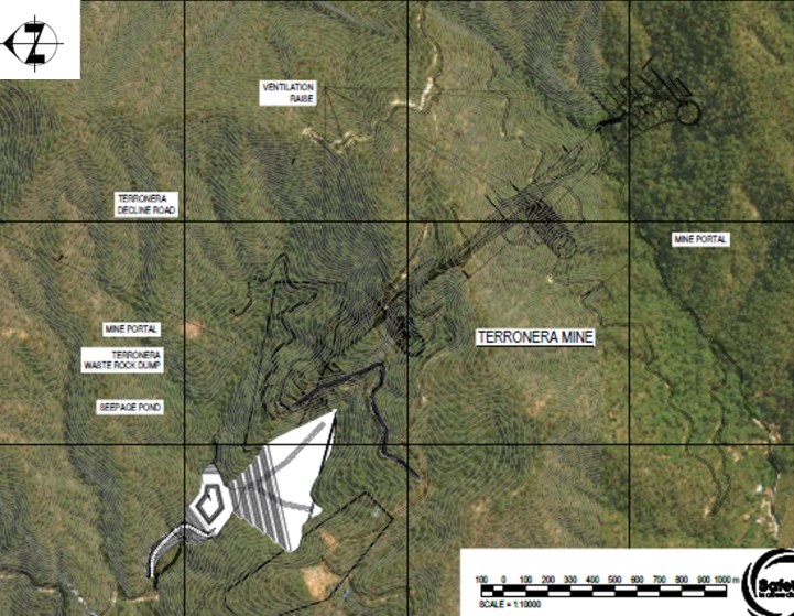
Source: Ausenco, June 2020
Figure 16-3 Terronera and La Luz Plan View
16.2 Geotechnical Considerations
16.2.1 Geotechnical Characterization
Geotechnical characterization programs were carried out by KP during2019 in order to provide guidance on geotechnical design parameters for the proposed underground mines. The programs consisted of detailed geotechnical logging and orientation of core retrieved from three drill holes at Terronera (2016) and four drill holes at La Luz (2018-2019). In total, the programs included 1,970 m of geotechnical drilling and 1,535 m of detailed geotechnical logging.
Logging parameters were collected to characterize rock mass conditions according to the Bieniawski (1989) rock mass rating (RMR) and the Barton Q (Barton & Grimstad, 1993) rock mass classification systems. Field estimates of uniaxial compressive strength (UCS) were made during the logging program using a Schmidt Hammer according to the ASTM D5873 standard. JDS reviewed the geotechnical logging database and spot checked data against respective core photographs to confirm data quality and internal consistency. JDS also estimated geotechnical logging parameters of the hanging wall, footwall and vein intervals for several resource core holes based on core photographs.
Following the KP geotechnical logging programs, representative core samples from the various rock types were shipped to Wood for laboratory strength testing. The overall test programs included 35 UCS tests, 21 triaxial compressive strength (TCS) tests and 27 Brazilian indirect tensile strength (BTS) tests. It was not possible to collect samples of sufficient length for testing within the Terronera vein due its heavily fractured nature.
16.2.2 Geotechnical Domains and Rock Mass Properties
Using primarily the geotechnical core logging data, resource core logging RQD database, and core photographs, the deposit was divided into geotechnical domains. Each individual domain groups large volumes of rock anticipated to possess similar ground conditions and overall rock mass quality which are used as the basis for developing geotechnical design parameters. Geologic fault structures were identified as the dominant factors controlling the rock quality domains.
Based on review of the KP 2019 rock mass characterization which was assessed primarily by lithology, the rock mass quality data was analyzed by proximity to the mineralized vein. The initial zones assessed consisted of the mineralized vein material and the immediate (20 m to 30 m) hanging wall and footwall.
Further review of the geotechnical characterization data suggested that the Terronera deposit could be domained in order to define areas potentially suitable for LH stoping. The domaining focused specifically on the poor rock mass quality commonly observed within fault zones located adjacent to, and/or near, the vein contacts. Three-dimensional fault surfaces were created by Endeavor Silver staff by linking these fault zones between drill holes. JDS spot checked the faults surfaces and verified their reliability for the purpose of the UPFS geotechnical design.
The geotechnical domaining indicates that, overall, the rock mass distal to the Terronera vein is typically of good geomechanical quality with relatively high intact strengths and few fractures. The hanging wall andesite and footwall rhyolite in these areas have average UCS strengths of 225 MPa and 90 MPa, respectively, based on the KP (2019) investigation.
Due to reactivation of the faults on either side of the vein after its emplacement, numerous fault zones exist paralleling the vein either at or near the contact. The rock quality in these fault zones is typically poor to very poor. Similarly, the Terronera vein material is typically heavily fractured or crushed due to the post mineralization displacements along the hanging wall and footwall structures. As such, it was not possible to collect samples at Terronera that were of sufficient length for laboratory testing.
The Footwall Fault is an effectively continuous zone of heavily damaged rock starting at or near the contact and can extend for a few meters up to tens of meters. The Hanging Wall Fault zones are similarly poor in rock quality, but are not as pervasive as the Footwall Fault, and appear to be constrained within certain areas of the vein.
Based on the spatial distribution of the Hanging Wall Fault and its inherently poor to very poor ground conditions, the Terronera vein was separated into three domains: the Southeast, Central and Northwest domains as shown on Figure 16-14.
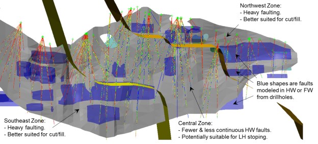
Source: JDS, 2020
Figure 16-4 Schematic Section Showing Terronera Geotechnical Domains (Oblique View Looking Southwest)
Ground conditions in the immediate hanging wall of the Northwest and Southeast domains are typically poor to very poor with weak and heavily fractured rock due to the presence of the Hanging Wall Fault. The fault is much less persistent within the Central domain resulting in improved hanging wall rock mass quality with less fracturing and higher intact rock strengths on average.
The geotechnical core logging data suggest better overall ground conditions at La Luz than at Terronera. The average UCS strength of the distal hanging wall and footwall andesite at La Luz are 135 MPa and 115 MPa, respectively. The mineralized vein is also typically more competent with an average UCS of 125 MPa based on the KP (2019) investigation. Occasional faulting, and fractured, weak rock still occurs in the La Luz footwall but these are less common. The mineralized vein is also typically more competent.
Histograms of rock mass classification parameter Q’ are shown in Figure 16-5 and Figure 16-6 for the immediate hanging wall and footwalls and vein of the Terronera and La Luz veins, respectively.
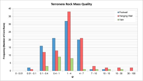
Source: JDS, 2020
Figure 16-5 Distribution of Terronera Rock Mass Quality Parameter Q’
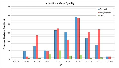
Source: JDS, 2020
Figure 16-6 Distribution of La Luz Rock Mass Quality Parameter Q’
16.2.3 In-Situ Stresses
The magnitude and direction of in-situ stresses near the Terronera site have not been directly measured. No observations were made underground indicating high horizontal stress conditions; however, historic workings are very small and near surface.
Stress conditions have been estimated based primarily on the World Stress Map (Heidbach, et al, 2016) as well as regional geologic information and site topographic features. The World Stress Map estimates obtained closest to the Terronera site are shown on Figure 16-7 and were calculated from single focal mechanism earthquake events.
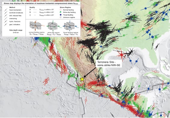
Source: JDS, 2020
Figure 16-7 Estimated Stress Orientation
The focal sources in the area are rated as ‘C’ quality (± 25° accuracy) and indicate a thrust faulting regime which is consistent with the nearby Pacific-North American plate subduction zone. The nearby sources indicate maximum horizontal stress (☐1) direction oriented approximately 030° azimuth which is approximately perpendicular to the strike of the veins.
It is assumed that the maximum horizontal stress magnitude is relatively low given the shallow (200-400 m) depth of the majority of the planned stoping areas. The deepest portion of the Terronera vein extends to a depth of approximately 525 m below ground surface.
It has been conservatively assumed for the UPFS analyses that the ratio of maximum horizontal stress (☐H) to vertical stress (☐v) is approximately two, with the maximum horizontal stress oriented perpendicular to the vein strike. The minimum horizontal stress (☐h) has been assumed to be approximately 1.5 times vertical stress (☐v). The anticipated range of stresses has been considered in the calculation of stress parameter A for stope design as discussed below. Horizontal stresses may require more detailed assessment during operation.
16.2.4 Empirical Stope Design Analysis
Empirical stope design analyses are based on stability graphs where the stability number (N’) is plotted on the vertical axis against the hydraulic radius (wall area divided by wall perimeter) of the stope face on the horizontal axis. The stability number is calculated based on Q’, and three empirical factors: A (induced stress conditions), B (geologic structure orientation) and C (dip angle of the stope face).
Maximum stope dimensions were estimated using the Potvin (2001) method for the anticipated range of rock mass conditions and stope sizes. The Trueman & Mawdesley (2003) ‘Stable’ line was used as a check against the Potvin (2001) results. Upper and lower bound estimates of stope face dimensions and Q’ were analyzed for the hanging wall, footwall and vein materials for the Terronera and La Luz veins. The design upper and lower bound estimates of Q’ are summarized for the Terronera and La Luz veins in the tables at the top of Figure 16-8 and Figure 16-9, respectively.
Empirical factors for the calculation of N’ were based on the following assumptions:
• Mining induced stress parameter (Factor A) ranging between 0.6 and 0.8, based on the relatively strong UCS (90 to 250 MPa) and low anticipated horizontal stress.
• Dominant joint set orientation parameter (Factor B) ranging between 0.3 and 0.5 for the hanging wall and footwall, based on the dominant discontinuity orientation being sub-parallel to veins.
• Gravity parameter (Factor C) was calculated for each stope wall based on its dip angle using the equation: C =8 – 6 * cos (face dip angle). The maximum value of eight was assumed for the footwall gravity factor due to its favorable orientation.
A maximum level spacing of 20 m was initially assumed and then the resulting maximum strike lengths and widths were then determined from the stability graph for the hanging walls and backs, respectively. Figure 16-8 and Figure 16-9 contain output plots from the empirical stability analysis for the Terronera and La Luz longitudinal stopes, respectively. Based on the analyses, a maximum stable hanging wall strike length of 15 m is estimated for the Terronera and La Luz veins, based on 20 m and 16 m level spacings, respectively.
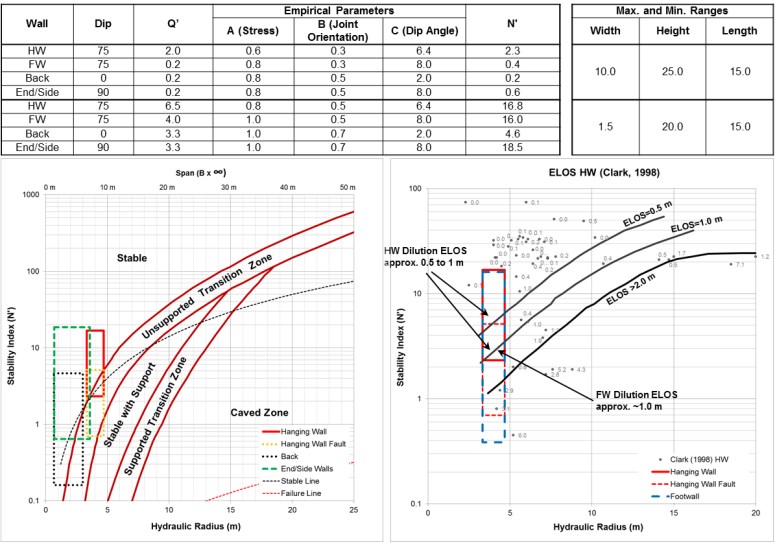
Source: JDS, 2020
Figure 16-8 Empirical Stope Stability and Dilution Charts for Terronera Longitudinal LH Stopes
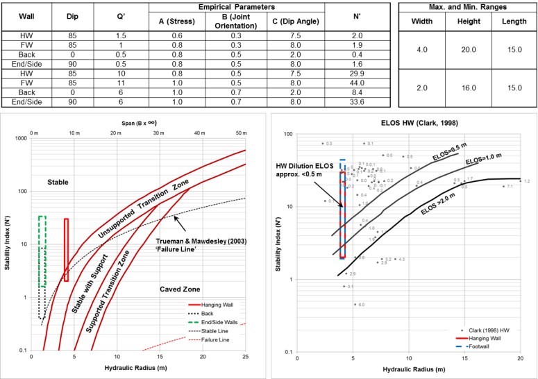
Source: JDS, June 2020
Figure 16-9 Empirical Stope Stability and Dilution Charts for La Luz Longitudinal LH Stopes
16.2.5 Estimates of Unplanned Dilution
The potential for unplanned dilution was estimated for stope hanging walls and footwalls using the Equivalent Linear Overbreak/Slough (ELOS) method developed by Clark (1998). The method is similar to the empirical stope stability charts previously discussed with N’ plotted on the vertical axis and the hydraulic radius (wall area divided by wall perimeter) of the stope face on the x-axis but rather than showing stable/unstable conditions, the plot contains contours of unplanned dilution. The estimates are approximated in terms of the average thickness spread over the entire hanging wall or footwall. The ELOS graph is not applicable to small hydraulic radii (<4). For small hydraulic radii such as these, the quality of blasting practices is typically the primary control on dilution.
Based on Figure 16-8 and Figure 16-9, unplanned dilution for Terronera LH stopes is anticipated to be 0.8 m for the hanging wall and 1.0 m for the footwall due to the significantly poorer rock quality associated with the Footwall Fault. The La Luz LH stopes are anticipated to be controlled primarily by blasting practices and as such, have been estimated based on anticipated blasting and excavation practices for those areas. For the UPFS, unplanned dilution for the La Luz LH stopes is estimated to be 0.3 m for the hanging walls and 0.5 m for the footwalls due to the poor rock quality associated with the Footwall Fault, where present.
16.2.6 Backfill Strength Requirements
Stopes are planned to be backfilled with cemented paste backfill that will provide confinement on the stope walls. The use of cemented backfill also enables adjacent stopes to be mined up against backfilled stopes without having to leave a rib pillar to retain the backfill.
Requirements for the cemented paste backfill UCS strength were developed analytically for various stope widths using the simplified wedge analysis method originally developed by Mitchell (1983). Results of the analysis are summarized in Table 16-1 for an overall stope height of 25 m (20 m stope and 5 m top cut) and assuming a 2.0 safety factor. A factor of safety of 2.0 is conservative compared to some operating mines but is considered appropriate for a PFS level of study. It may be possible to reduce the safety factor to 1.5 or 1.3 during operation once specific experience with the site materials has been gained.
Table 16-1 Required UCS for Various Stope Widths
Stope Width | % of LH Stopes | Design Backfill UCS |
3-<5 | 36 | 138 |
5-<8 | 36 | 194 |
8-<11 | 18 | 265 |
11-<15 | 6 | 342 |
15-20 | 2 | 412 |
>20 (35 to 40) | 0 | 599 |
Numerical stress modeling may be advantageous at a later stage of study or during operation when more detailed backfill and rock mass information are available; however, detailed modeling of backfill is not recommended at the current level of study.
16.2.7 Ground Support
Based primarily on the anticipated range of Q’ values and the size of the openings, ground support requirements were initially designed according to the Barton & Grimstad (1993) criteria as shown on Figure 16-10.
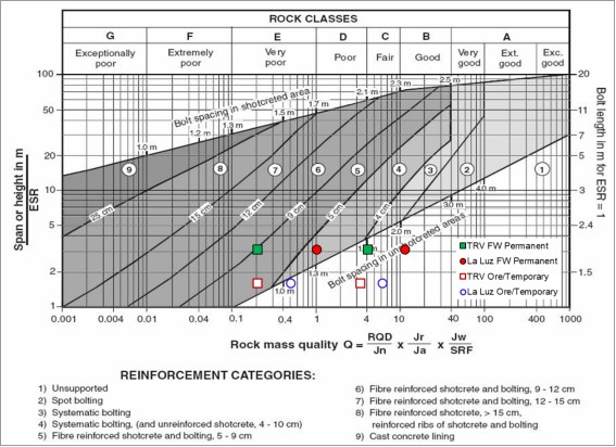
Source: Grimstad & Barton, 1993
Figure 16-10 Barton’s Q Ground Support Chart
The Q-system also accounts for the life and anticipated usage of the opening (ex. man-entry or equipment only) with the excavation support ratio (ESR) parameter. The ESR is used to adjust the design span, in order to obtain the equivalent span for use in the Q support diagram; in effect, it imposes a higher factor of safety on critical structures with long life (such as an underground nuclear power station with an ESR rating of 0.5 to 0.8) than on temporary tunnels (such as temporary mine workings with an ESR rating of 2 to 5). An ESR of 1.6 was used for permanent development and temporary while ore development was assessed assuming an ESR of 2.5. An ESR of 4 might typically be used for short term ore development; however, given the retreat method being used and the inherently longer life span required, the ESR was decreased to 2.5 for the analyses.
For the purposes of the UPFS, ground support types are recommended based on the life span of the development (short term or long term) for the three types of ground conditions: Very Poor, Poor and Fair to Good. The estimated percentage of the three types of ground conditions are summarized in Table 16-2 with the respective ground support recommendations for each type summarized.
Table 16-2 Estimated Percentage of Ground Types
Vein | Development Type | Type 1 | Type 2 | Type 3 |
Terronera | Vein/Temporary | 40% | 40% | 20% |
Footwall /Permanent | 30% | 30% | 40% | |
La Luz | Vein/Temporary | 0% | 15% | 85% |
Footwall /Permanent | 5% | 20% | 75% |
Ground support recommendations are as follows:
• Temporary/ore development (4 x 4 m):
o Very Poor Ground (Type 1): 6 cm fiber reinforced shotcrete, floor to floor and 1.8 m long split sets at 1.5 m spacing.
o Poor Ground (Type 2): 1.8 m long split sets with 12 inch plates at 1 m spacing with welded wire mesh from floor to floor.
o Fair to Good Ground (Type 3): 1.8 m long split sets with 6 inch plates at 1.2 m spacing with welded wire mesh to 1.5 m from floor.
• Long-term/footwall development (5 x 5 m) are as follows:
o Very Poor Ground (Type 1): 6 cm fiber reinforced shotcrete, floor to floor and galvanized 1.8 m long split sets at 1.2 m spacing.
o Poor Ground (Type 2): 1.8 m galvanized split sets with 12 inch plates at 1 m spacing with welded wire mesh from floor to floor.
o Fair to Good Ground (Type 3): 2.4 m long galvanized split sets with 6 inch plates at 1.2 m spacing with welded wire mesh to 1.5 m from floor to floor.
16.3 Backfill
Backfill that will be used at the Terronera and La Luz deposits will be one of two types: cemented or uncemented rock fill. Uncemented rock fill (UCF) will be composed of either development waste or quarried rock. Cemented rock fill (CRF) will be composed of crushed development waste or quarried waste, sized to <100 mm and mixed with a portion of grey (Portland) cement binder. This binder content will be either 4% by mass for areas to be laterally exposed in future workings but not undercut, or 8% by mass for areas to be undercut by future workings. Any areas that will not be either laterally exposed or undercut will be filled with UCF material. All backfill will be trucked to a local remuck and placed by load-haul-dump (LHD) vehicles.
Insufficient development waste material exists to fill the required production voids. It is expected that 1.47 Mt of rock will need to be quarried from Year 7 until the end of mine life to supplement the development waste.
It is expected that 139 kt of cement will be consumed in the CRF backfill throughout the life of the mine.
16.4 Waste Development
It is expected that all waste development outside of production areas will be performed by contractors using equipment provided by Endeavour Silver, with the exception of haul trucks and raisebore units, which will be provided by their respective contractors or by Endeavour Silver, at Endeavour Silver’s discretion.
16.4.1 Lateral Development
Main lateral waste development will be performed with 2-boom jumbos, 10-t class LHDs, and mechanized bolters. This development will include all parts of the ramp and level up to the start of the attack ramp, excluding the orepass access on levels with an orepass. Haulage will be performed with 14.5 m3 class low profile underground haul trucks. The same equipment will be used at both deposits, and it is envisioned that the fleet will be shared between the deposits as required.
A summary of lateral waste development meters by type is provided in Table 16-3.
Table 16-3 Lateral Waste Development Meter Summary
Deposit | Drift Type | Nominal Dimensions (m) | Total Mine Development (m) |
Terronera | Permanent Waste Drives | 5.0 W x 5.0 H | 21,381 |
Temporary Waste Drives | Varies | 11,887 | |
Development Ore Drives | 4.0 W x 3.5 H | 8,471 | |
Sub-total | Varies | 41,739 | |
La Luz | Permanent Waste Drives | 5.0 W x 5.0 H | 3,831 |
Temporary Waste Drives | Varies | 328 | |
Development Ore Drives | 2.4 W x 3.3 H | 2,471 | |
Sub-total | Varies | 6,630 | |
Total | Permanent Waste Drives | 5.0 W x 5.0 H | 25,212 |
Temporary Waste Drives | Varies | 12,215 | |
Development Ore Drives | 4.0 W x 3.5 H | 10,942 | |
Total Lateral Meters | 48,369 | ||
* Equivalent meters based on slashed volumes.
16.4.2 Vertical Development
Vertical development will be a combination of raisebore and drop raise development. A specialized contractor will be brought in to raisebore ventilation raises at 3.1 m diameter, orepasses at 2.4 m diameter, and escapeways at 1.2 m diameter. For other vertical development, a Long hole drill will be used to drill a drop raise for ventilation or material handling.
At Terronera, for scheduling reasons, ventilation raises above the 1380EL truck drift will be driven with a raisebore, and all ventilation raises below the 1380EL truck drift will be drop raised at 4.0 m x 4.0 m with a longhole drill, with the exception of the M1 lower vent raise. All orepasses will be driven with a raisebore, with all fingers drop raised with the longhole drill. To ensure proper blasting of these parts of the raises, electronic detonators will be used. Escapeways above the 1380EL truck drift will be driven with a raisebore, and escapeways below will be timbered compartments within the drop-raised vent raises, with the exception of the M1 lower escapeway. This will require drawing down the waste from the blast and supporting the entire raise.
A summary of vertical waste development meters by type is included in Table 16-4.
Table 16-4 Vertical Waste Development Meter Summary
Deposit | Drift Type | Nominal Dimensions (m) | Total Mine Development (m) |
Terronera | Alimak Raises (vent raises) | 2.4 W x 2.4 H | 690 |
Raisebore Raises (escapeways) | 3.1m dia. | 720 | |
Drop Raises (ore passes) | 1.2 dia. | 1,749 | |
Sub-total | 3.1m dia. | 3,160 | |
La Luz | Alimak Raises (vent raises) | 2.4 W x 2.4 H | 231 |
Raisebore Raises (escapeways) | 3.1m dia. | 231 | |
Drop Raises (ore passes) | 1.2 dia. | 0 | |
Sub-total |
| 231 | |
Total | Alimak Raises (vent raises) | 2.4 W x 2.4 H | 922 |
Raisebore Raises (escapeways) | 3.1m dia. | 720 | |
Drop Raises (ore passes) | 1.2m W x 1.2m H | 2,701 | |
Total Vertical Meters | 3,391 | ||
16.5 Longhole Retreat Mining with Backfill
Longhole retreat mining will be used in both the Terronera and La Luz deposits where applicable. Each cycle of longhole mining will be followed by fill placement.
Longhole mining will take place by accessing the stoping areas with waste ramps from the footwall. Once encountering the ore, a sill cut, on multiple sublevels will be driven to both longitudinal extremities of the ore zones. Once the ore zone extremities have been reached, longhole drilling from the upper sublevel to the lower sublevel will take place and a slot will be developed at the end of the designated stoping block followed by regular longhole drilling throughout the stope block proper. The stope will be developed to a length appropriate to the geotechnical parameters, is this case 15 m long. Long hole blasting will then be carried out, starting with the slot, then the rest of the ore body until the designated length is reached. Mucking with 3.0 m3 LHDs will be carried out from the lower sublevel, in remote-controlled fashion as required, until the stope has been mucked clean.
At this point, high-cement content rock fill will be placed in the lower sublevel at the entrance to the stope, then the rest of the stope will be filled with CRF of a lower cement level, or, if conditions dictate, no cement at all. All filling will be carried out from the top sublevel with LHD units mucking backfill from the remuck close to the ramp. Backfill may also be placed using haul trucks driving directly to the open stope and placing backfill with their ejector trays. This would reduce the cycle time for placing backfill. Once a stope has been filled, the cycle will be repeated, first by continuing to retreat with the next longitudinally adjacent panel until reaching the last panel, which will be access by the ramp, at which point, the cycle will be repeated by mining the next set of sublevels located vertically above the first set of sublevels.
16.6 Mechanized Cut and Fill Mining
MCF involves the excavation of ore material from a cut, followed by placement of backfill to allow for mining of the next vertical lift. The backfill material will be rock fill or quarry rock, consolidated or unconsolidated, depending on its intended application. Numerous sub-types of MCF mining exist. This method will be used where the veins lie flatter or where the ground is too faulted to open it up for longhole retreat mining.
With MCF mining, the ore body is accessed from the footwall through a waste crosscut. When the ore is encountered, drifting along the ore (taking the sill cut) until the reaching the end of the stope is carried out. Once this sill cut is completed, it will be backfilled with either cemented or uncemented rockfill or quarry rock to provide a working platform for the next lift. However, the stope will not be tight-filled to the back (roof). A small void (approximately 0.5-0.6 m high vertically) will be left to provide void for the level above to be blasted into, thus removing the need for drilling a cut on the drift above.
Where an artificial sill pillar is required, the sill cut will be filled with 8% CRF so that MCF can take place lower in the deposit, working up to and under this concrete-reinforced fill. Filling practices above this (4% CRF for future lateral exposure, UCF for unexposed areas) will be carried out for the remainder of the mining cycle.
Generally, each MCF stope will comprises five « lifts » to create a nominal level spacing of 20 m; however, certain areas may have more, or fewer, lifts as required for mining operations. Drift widths are generally optimized for a 6.7-t class LHD unit and are at least 3.0 m wide, however in certain areas where thin cuts are required, a 3.5-t class LHD will be used in drifts as narrow as 2.1 m wide.
Each lift will be 200-450 m long and will be accessed via attack ramps from the closest principal ramp. The set of attack ramps will intersect the stoping block centrally, subdividing the first lift into two working areas extending 100-250 m along strike and repeating this pattern for subsequent lifts. The maximum gradient of the attack ramps will be ±15%. As each lift is completed, the back (roof) of the attack ramp will be slashed out to provide access to the lift above, and the process will repeat until the level is completed, at which point mining operations will relocate to the level above. All drift-and-fill mining operations will progress within a level in an overhand fashion to limit the requirements for personnel to access areas underneath consolidated fill. The minimum mining width of the equipment planned to be use at Terronera is 2.1 m, making the drift-and-fill method an inappropriate choice due to excessive dilution of the vein.
16.6.1 Resue Mining
The La Luz deposit consists of a single narrow vein which rarely exceeds 1 m in width and is normally significantly narrower. Resue mining, where the ore from the lift above is mined from the lift below prior to mining the waste and filling the drift below, has therefore been selected to reduce dilution, use the same mining fleet between Terronera and La Luz, and reduce the overall mining costs of the La Luz vein by reducing both the amount of waste that must be hauled out of the stope and the amount of backfill that will later be required to be placed within the stope.
Resue mining at La Luz will begin with the excavation of a main level, with an attack ramp at a maximum gradient of ±15% connecting to the centre of the lowest lift in a mining level, dividing the lift into two approximately 150 m-long sections. Normal drifting methods will be used on the lowest lift in each level to excavate a void for mining the next lift above. All material from this lift will be treated as ore and sent to the plant. Once the excavation is complete, a production drill jumbo will be used to drill holes vertically upward along the ore contact in the roof to blast the ore from the lift above down into the void in the excavated lift below. This material will then be excavated using a 6.7-t class LHD, after which the trench in the roof will be supported, and then the waste in the lift above (including the roof of the attack ramp) will be drilled and blasted down into the lift below in a similar manner to the ore. This waste will form the floor of the next lift but may require additional backfill to bring it to the required floor level of the next lift. After supporting the newly excavated lift, the process will repeat in an overhand fashion until the level is exhausted.
Where the mining level is going to become an artificial sill pillar, all waste from the resue will be excavated and replaced with CRF comprising 8% cement by mass to create the artificial pillar until the required thickness is reached.
16.7 Representative Drawings
Representative drawings of mining levels are included as Figure 16-11.
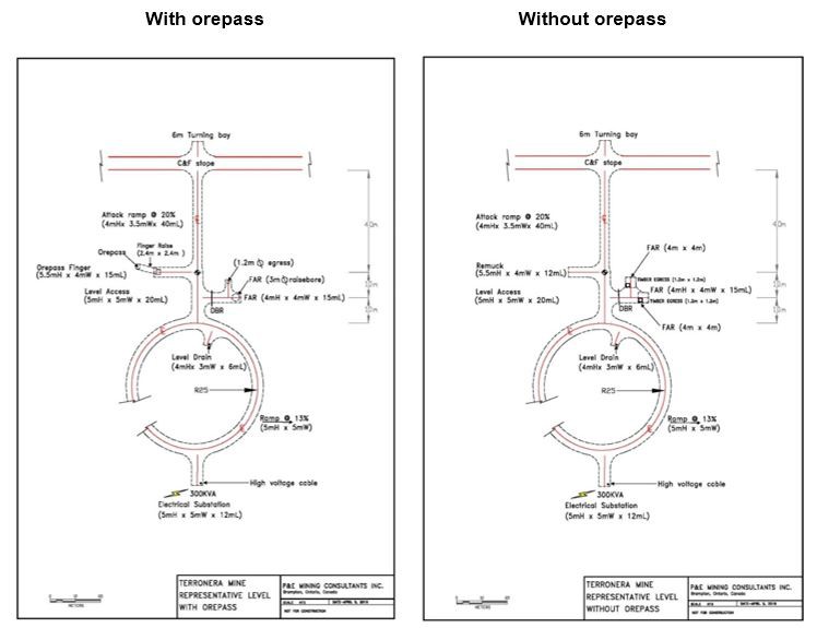
Figure 16-11 Representative Level Drawings
16.8 Schedules
16.8.1 Development
The lateral waste development schedule is provided in Table 16-5. Waste will be mined from Year -2 to Year 10.
16.8.2 Production
The production schedule by mining method is included in Table 16-6. There will be a two-year pre-production period and a 10-year LOM.
Table 16-5 Lateral Waste Development Schedule by Type and Period (m)
Year | -2 | -1 | 1 | 2 | 3 | 4 | 5 | 6 | 7 | 8 | 9 | 10 | Total |
Project Totals | |||||||||||||
Lateral Development | |||||||||||||
Total – Permanent Waste Drives | 3,195 | 7,272 | 5,801 | 4,607 | 1,751 | 1,609 | 891 | – | – | 36 | 50 | – | 25,212 |
Total – Temporary Waste Drives | 203 | 550 | 1,502 | 1,406 | 1,626 | 1,718 | 1,539 | 1,371 | 1,132 | 796 | 320 | 53 | 12,215 |
Total – Development Ore Drives | 128 | 2,269 | 2,484 | 1,707 | 932 | 480 | 1,119 | 530 | 257 | 438 | 473 | 126 | 10,942 |
Total Lateral Development | 3,526 | 10,090 | 9,786 | 7,720 | 4,308 | 3,807 | 3,549 | 1,902 | 1,389 | 1,269 | 843 | 179 | 48,369 |
| |||||||||||||
Vertical Development | |||||||||||||
Total – Vent Raise | 237 | 118 | 111 | 167 | 107 | 97 | 84 | – | – | – | – | – | 922 |
Total – Escape Way | – | – | 352 | 145 | 223 | – | – | – | – | – | – | – | 720 |
Total – Ore Pass | – | 207 | 35 | 1,015 | 429 | 38 | 25 | – | – | – | – | – | 1,749 |
Total Vertical Development | 237 | 325 | 498 | 1,327 | 760 | 135 | 109 | – | – | – | – | – | 3,391 |
| |||||||||||||
Terronera | |||||||||||||
Horizonal Development | |||||||||||||
Terronera – Permanent Waste Drives | 2,060 | 5,186 | 5,191 | 4,607 | 1,751 | 1,609 | 891 | – | – | 36 | 50 | – | 21,381 |
Terronera – Temporary Waste Drives | 147 | 538 | 1,242 | 1,406 | 1,626 | 1,718 | 1,539 | 1,371 | 1,132 | 796 | 320 | 53 | 11,887 |
Terronera – Development Ore Drives | – | 796 | 1,624 | 1,697 | 932 | 480 | 1,119 | 530 | 257 | 438 | 473 | 126 | 8,471 |
Sub-total Lateral Development | 2,207 | 6,520 | 8,057 | 7,710 | 4,308 | 3,807 | 3,549 | 1,902 | 1,389 | 1,269 | 843 | 179 | 41,739 |
| |||||||||||||
Year | -2 | -1 | 1 | 2 | 3 | 4 | 5 | 6 | 7 | 8 | 9 | 10 | Total |
Vertical Development | 119 | 20 | 97 | 167 | 107 | 97 | 84 | – | – | – | – | – | 690 |
Terronera – Vent Raise | – | – | 352 | 145 | 223 | – | – | – | – | – | – | – | 720 |
Terronera – Escape Way | – | 207 | 35 | 1,015 | 429 | 38 | 25 | – | – | – | – | – | 1,749 |
Terronera – Ore Pass | 119 | 226 | 484 | 1,327 | 760 | 135 | 109 | – | – | – | – | – | 3,160 |
Sub-total Vertical Development |
|
|
|
|
|
|
|
|
|
|
|
|
|
| |||||||||||||
La Luz | |||||||||||||
Horizontal Development | |||||||||||||
La Luz – Permanent Waste Drives | 1,135 | 2,085 | 610 | – | – | – | – | – | – | – | – | – | 3,831 |
La Luz – Temporary Waste Drives | 56 | 12 | 260 | – | – | – | – | – | – | – | – | – | 328 |
La Luz – Development Ore Drives | 128 | 1,473 | 860 | 10 | – | – | – | – | – | – | – | – | 2,471 |
Sub-total Lateral Development | 1,320 | 3,571 | 1,730 | 10 | – | – | – | – | – | – | – | – | 6,630 |
| |||||||||||||
Vertical Development | |||||||||||||
La Luz – Vent Raise | 119 | 99 | 14 | – | – | – | – | – | – | – | – | – | 231 |
La Luz – Escape Way | – | – | – | – | – | – | – | – | – | – | – | – | – |
La Luz – Ore Pass | – | – | – | – | – | – | – | – | – | – | – | – | – |
Sub-total Vertical Development | 119 | 99 | 14 | – | – | – | – | – | – | – | – | – | 231 |
Table 16-6 Production Stopping Schedule by Mining Method
Year | -2 | -1 | 1 | 2 | 3 | 4 | 5 | 6 | 7 | 8 | 9 | 10 | Total |
Project Totals | |||||||||||||
Total – Long hole Stoping | – | – | 201,717 | 180,078 | 84,170 | 90,537 | 78,689 | 116,884 | 207,527 | 304,639 | 380,675 | 402,126 | 2,047,042 |
Total – Cut & Fill | – | 43,447 | 195,142 | 347,350 | 465,221 | 466,762 | 455,386 | 437,873 | 355,253 | 256,933 | 130,786 | 28,215 | 3,182,367 |
Total – Resue Cut & Fill | – | 365 | 10,081 | 508 | 197 | – | – | – | – | – | – | – | 11,150 |
Total – Development Ore | 1,386 | 55,453 | 56,286 | 52,553 | 31,400 | 18,696 | 41,913 | 21,279 | 13,287 | 13,664 | 12,908 | 3,611 | 322,437 |
Total – Production | 1,386 | 99,265 | 463,227 | 580,489 | 580,988 | 575,995 | 575,988 | 576,036 | 576,066 | 575,237 | 524,369 | 433,952 | 5,562,997 |
Terronera | |||||||||||||
Terronera – Long hole Stoping | – | – | 157,266 | 76,010 | 71,963 | 90,537 | 78,689 | 116,884 | 207,527 | 304,639 | 380,675 | 402,126 | 1,886,317 |
Terronera – Cut & Fill | – | 43,447 | 195,142 | 347,350 | 465,221 | 466,762 | 455,386 | 437,873 | 355,253 | 256,933 | 130,786 | 28,215 | 3,182,367 |
Terronera – Resue Cut & Fill | – | – | – | – | – | – | – | – | – | – | – | – | – |
Terronera – Development Ore | – | 27,123 | 50,571 | 52,553 | 31,400 | 18,696 | 41,913 | 21,279 | 13,287 | 13,664 | 12,908 | 3,611 | 287,006 |
Terronera – Production | – | 70,570 | 402,980 | 475,913 | 568,584 | 575,995 | 575,988 | 576,036 | 576,066 | 575,237 | 524,369 | 433,952 | 5,355,689 |
La Luz | |||||||||||||
La Luz – Long hole Stoping | – | – | 44,451 | 104,068 | 12,207 | – | – | – | – | – | – | – | 160,725 |
La Luz – Cut & Fill | – | – | – | – | – | – | – | – | – | – | – | – | – |
La Luz – Resue Cut & Fill | – | 365 | 10,081 | 508 | 197 | – | – | – | – | – | – | – | 11,150 |
La Luz – Development Ore | 1,386 | 28,330 | 5,715 | – | – | – | – | – | – | – | – | – | 35,431 |
La Luz – Production | 1,386 | 28,695 | 60,247 | 104,576 | 12,404 | – | – | – | – | – | – | – | 207,307 |
16.9 Services
16.9.1 Ventilation
After initial development, which is ventilated by auxiliary ventilation, fresh air for Terronera and La Luz will be supplied from surface via 3.1 m diameter ventilation raises driven by a raise bore machine: four at Terronera and one at La Luz.
Single surface fans (similar to Hurley 72-50-900 units) of 1.83 m diameter powered by 184 kW motors will provide airflow to the underground operations. La Luz is expected to require roughly 71 cms of airflow at peak production, whereas the Terronera will require roughly 135 cms at peak production. Initial adit development will be ventilated by 2 x 75 kW fans in series forcing air through Mecanicad-type semi-rigid ventilation ducting.
Each mining block in the Terronera deposit will be ventilated with its own fresh air raise that will provides air directly to the level from surface. Air will be forced out of the raise through a regulator, then exhausted up to (for levels below), or down to (for levels above), the 1380 truck haulage drift, where it will exhaust back to the West Terronera portal. Additionally, air will be exhausted into the main haulage drift and out through the process plant portal.
The fresh air raise for the La Luz deposit will be connected directly to the upper levels of the M7 mining block, with its toe connecting to a ventilation transfer drift running parallel to the haulage ramp until it reaches the top of the lower M7 ventilation raise, which will be drop raised from level to level. Once out of the raise, the air will return out the portal via the haulage ramp in a similar fashion to that proposed for ventilation at Terronera. No levels at the planned La Luz mine will exclusively rely on auxiliary ventilation.
16.9.2 Electrical
The La Luz mine will run on diesel-generated power. A genset sufficiently far from the portal will be set up to generate 5 kV power that will be brought into the mine via the ramp. In the mine, power will be reduced by transformers that will be installed in cut-outs opposite the active levels to 440 V and will be moved as necessary when levels are completed.
For the Terronera mine, power will be supplied from the local power grid and will be transmitted via a 13.8 kV high-voltage cable along surface and, prior to entering the mine via ramps and raises will be transformed to 5 kV, until it reaches the substations underground, where it will be stepped down to 440 V.
16.9.3 Dewatering
All active mining faces will be dewatered using compressed air pumps (similar to Wilden PX series pumps) pumping to 100 mm pipes to level sump cutouts.
The dewatering system will use cascading sumps. Drill holes connecting small level sumps will drain either to main sumps on the 1380 EL haulage level (for levels above the drift) or to mining block sumps at the bottom of the spiral ramps (for levels below). Block sumps will pump water through 150 mm pipes in drill holes to the main haulage level sump, where the solids will be decanted and clean water will be returned to the mine water system. Dirty water from the main sump will be pumped along the haulage drift and out the portal through 150 mm diameter pipes. The dewatering system is designed to pump a maximum of 64 L/s to surface under flood conditions. Excess water will be pumped to the process plant portal.
The dewatering system for the La Luz operation will use a similar system as that proposed for the Terronera mine. All levels in the upper block will drain via cascading sumps to a main sump in the ventilation transfer drift, and all levels in the lower block will drain to a lower sump that will pump through 150 mm pipes in drill holes to the main sump, where solids will be decanted off and clean water will be returned to the mine water system. Dirty water from the main sump will be pumped up the ramp and out the portal through 150 mm diameter pipes. The La Luz dewatering system is designed to pump a maximum of 20 L/s to surface under flood conditions. Excess water will be pumped to the La Luz main portal.
16.9.4 Compressed Air
Compressed air will be provided using 223 kW air compressors (similar to Sullair TS-32-300). It is expected that one compressor will be installed at La Luz and one compressor will be installed at Terronera, with an additional redundant spare compressor at Terronera. Compressed air will be distributed via a 150 mm line in the ramp, reducing in size as necessary when approaching the working face.
16.9.5 Egresses, Refuges and Additional Underground Infrastructure
A maintenance shop will be constructed underground on the 1380 m EL truck drift between the M8 and M9 mining blocks. Additionally, maintenance bays will be constructed near the train drift at the bottom of M5 and at the M6 intersection.
An explosives magazine will be constructed near the bottom of the ramp connecting the truck drift to the train haulage drift. All explosives for La Luz will be transported and stored in day boxes for use.
At Terronera, a refugee station equipped as a mine rescue base will be installed near the top of the ramp connecting the truck drift to the train haulage drift. This refuge will double as a lunch room, and will be equipped with all infrastructure and equipment necessary to function as a fresh air base for mine rescue operations. An additional lunch room will be installed at the underground shop between ramps M8 and M9. Smaller refuges will be installed throughout the mine as necessary; however, these are only expected to be used in the event of an emergency.
All levels at Terronera with raisebored ventilation raises will have a separate raisebored escapeway near the vent raise to allow a second means of egress in an emergency. For levels with drop-raised vent raises, a compartment will be timbered in the drop raise to allow emergency egress. Connector drifts between escapeways will be pressurized via the fresh air raise system to prevent the ingress of smoke or fumes in the event of a fire.
16.10 Equipment
The equipment proposed to mine the Terronera and La Luz deposits is included in Table 16-7.
Table 16-7 Development and Production Mining Equipment
Equipment Type | Similar To | Total Quantity Over LOM |
Underground Truck 30t/14.51 m3* | Sandvik TH430 | 7 |
Surface Truck (30.0t/15m3) | Caterpillar 730D | 2 |
3.5t/1.8m3 LHD | Sandvik LH203 | 2 |
6.7t/3.0m3 LHD | Sandvik LH307 | 4 |
10.0t/4.0m3 LHD | Sandvik LH410 | 3 |
6.7t/3.0m3 LHD Rammer Jammer | Sandvik LH307 | 3 |
FEL (11t/7.0cm) | Caterpillar 988H | 3 |
1-boom Production Jumbo | Sandvik DD211 | 5 |
2-boom Development Jumbo | Sandvik DD321 | 4 |
Bolting Jumbo | Sandvik DS311 | 4 |
Long hole Drill | Sandvik DL311 | 4 |
Scissor Deck | Getman A64 SL | 3 |
Explosive Loader | Getman A64 ExC | 4 |
Raiseborer** | Redbore 50, Redbore 70 | 1, 2 |
Jackleg/Stoper | PHQ-250 | 1 |
Infill Drill | Max 100m AQ wireline (CostMine) | 3 |
Small Explosives Truck | ANFO Loader Miller Equipment: ETrack 1300 w/basket | 2 |
Large Explosives Truck | Emulsion Loader: Getman, A64-ExC2-500 | 2 |
Shotcrete Sprayer – Mobile | Shotcrete Mobile – MacLean – SS2 | 4 |
Grout Pump | Grout Pump – Minepro – Kanuk | 1 |
Boom Truck | Boom Truck – Getman – A64 | 1 |
Backhoe | Backhoe – Miller – JCB 3CX | 1 |
Tractor | Tractor – Miller – JCB Etrac | 1 |
Telehandler | Telehandler – Miller – JCB 535-140 | 1 |
Utility Vehicle | Small Utility – Kubota – RTV900 | 1 |
Transmixer | Transmixer – MacLean – TM3 6m3 | 4 |
Mobile Rock Breaker | Mobile Rock Breaker – MacLean RB3 | 1 |
Grader | Grader – Miller – BG 100-M | 1 |
Mechanics Truck | Mechanics Truck – Miller – Toyota 1t Aerial Boom | 1 |
Fuel/Lube Truck | Fuel/Lube – Getman – A64-Lube | 1 |
Electrician Truck | Electrician Truck – Miller – Toyota 1t Flat deck | 1 |
Personnel Carrier | Crew Van – Miller – Toyota 1t Van | 1 |
Supervisor Truck | Miller – Toyota 1t Crew Cab | 2 |
Crew Van / Ambulance | Miller – Toyota 1t Van | 1 |
Excavator (4.5 m3) | Caterpillar 390F/PC800 | 1 |
Track Dozer | Caterpillar D6 | 1 |
Surface Grader | GD655 | 1 |
Portable Crushing & Screening Plant | 1.2 m dia cone crusher, 1.8 m x 6.1 m triple deck screen | 1 |
CRF Mixing Plant | Mixing Pit with Cement Mixer & Silo | 1 |
* Haulage trucks will be provided by the haulage contractor.
** Raiseborer will be provided by the raisebore contractor.
16.11 Material Handling
16.11.1 Ore Handling
At Terronera, the ore handling system is primarily designed to transfer ore via passes to the haulage drift leading to the stockpile in front of the primary crusher. All ore, including ore produced in the pre-production period, will be hauled by 30t/14.5 m3 low-profile underground haul trucks. All ore passes from all mining blocks will deliver ore to the haulage drift at the 1,210 m level.
At La Luz, all ore handling will be done with on-ramp loading of trucks of the same size used at Terronera. Level remuck bays are filled using 6.7t/3.0m3 LHD units. Ore and waste will then be mucked into the haul trucks using 10.0t/4.0m3 LHDs. Due to the low production rate of the deposit, it is unlikely that ramp traffic will be significantly impeded by this haulage arrangement.
All trucking of both ore and waste will be performed by a contractor.
16.11.2 Waste Handling
Development waste will be handled either directly into trucks or into ramp remuck stations and then rehandled into trucks. Main waste development will be mucked using 10.0-tonne LHDs. Attack ramp development and waste cross-cut development in production areas will be hauled to remuck bays via whichever sized LHD is driving the development (either 6.7-tonne or 10.0-tonne units depending on drift width) where it will be remucked into trucks using the 10.0-tonne class LHD units.
Waste development from the Terronera and La Luz operation will be stored at surface waste rock storage facilities (WRSFs) near the portals of each mine. For all WRSFs, the waste will eventually be returned to the mine as backfill. When possible during the mine life, waste will be trucked directly to active levels to be used as unconsolidated/uncemented backfill to limit haulage costs, although this was not built into this operating model.
The maximum mine waste stockpile at Terronera is expected to be approximately 800,000 t, occurring in Year 3, Month 1, whilst the maximum stockpile at La Luz is expected to be almost 300,000 t in Year 1, Month 10. From these respective dates, the stockpiles will steadily decline to the point where quarry rock will need to be supplied to the Terronera mine for backfill purposes.
16.11.3 Backfill Handling
For CRF, a trailer-mounted crushing and sizing system (similar to Metso G.A. NW106) fed by the surface loader will be used to generate a stockpile of sized material that will be loaded into the trucks directly from the crusher conveyor. These trucks will proceed to a nearby tank, mixer, and spray-bar assembly where their loads will be dosed with the appropriate quantity and concentration of cement solution for the load’s intended use (e.g. 8% by mass for CRF artificial sill pillars, 4% by mass for other CRF applications). The CRF will then be transported by truck to the remuck bay on the level where filling is taking place for either of the two mines. It is anticipated that some of the backfill will be able to be dumped directly into the stopes thus reducing backfill rehandled and reducing costs by not using LHD units to move the material into the stopes.
UCF will be loaded into trucks via a surface loader directly from the Terronera portal dump stockpile prior to transport to the level remuck. Some UCF is expected to consist of development waste and will be transported direct from the development face to the remucks underground without ever reaching the surface dump.
Backfill material in a level remuck will be rehandled by 3.5-t class or or 6.7-tonne class LHDs to the active stope being filled. The LHD size will be determined by the width of the drift.
Production of ore from the La Luz mine will start approximately 14 months before completion of the Terronera mill. During this period, ore from La Luz will be trucked to Endeavour Silver’s Bolanitas mill, located approximately 500 kms away and the ore will be processed under a toll milling arrangement.
Production from Terronera mine will begin five months before the start of the Terronera mill. During the ramp-up period, ore from Terronera mine will be stockpiled until an inventory of 70,000 t is built.
After commissioning of the Terronera mill, ore from both La Luz and Terronera mines will be blended and processed at the Terronera mill, achieving a production rate of 1,600 tpd within three months. When blended, 80% of the feed will be from the Terronera deposit. Over the life of the project, the mill is expected to be fed with largely a blend of La Luz and Terronera ores, however it is expected that there will be operational periods when the mill treats only Terronera ore.
17.1 Overall Process Design
The process plant design was developed using the comminution and flotation testwork data produced during the 2019 PFS. The majority of the testwork was completed on ore samples from the Terronera deposit, and only limited testwork was done on ore samples from La Luz.
In addition to the data from the 2019 testwork program, two composite samples from Terronera deposit were tested in 2020 to determine the primary grind size and to confirm the flotation circuit design. Results of the 2020 testwork were subsequently incorporated into the process design which forms the basis of this UPFS. As 95% of the feed source to the mill is anticipated to be from Terronera deposit, the mill design is based primarily on Terronera sample test data.
Testwork on samples from the La Luz deposit gave similar metallurgical results to samples from the Terronera deposit. For the purposes of the UPFS, the La Luz ore has been assumed to be comparable in metallurgical behaviour to the ores from Terronera, and no special adjustments to the process design have been provided to accommodate treatment of 100% of the feed to the mill from either deposit.
Design of the beneficiation plant at Terronera is based on three-stage crushing and single stage grinding to a target particle size of 80% passing 70 μm. Ground ores will be treated by flash flotation and conventional flotation with two stages of cleaning. On the basis of the testwork, overall recoveries of 84.9% for silver and 82.3% for gold are anticipated for the LOM. Precious metal values will be recovered into a flotation concentrate that may be sold in the open market. Flotation tailings will be filtered; and stored on surface in a tailings storage facility (TSF).
The plan of operation for the Terronera mill is to achieve the design capacity production rate of 1,600 tpd over a three-month ramp up period. At this design throughput, the LOM for the project is estimated at 10 years.
The overall process flow diagram of the proposed beneficiation plant is shown in Figure 17-1.
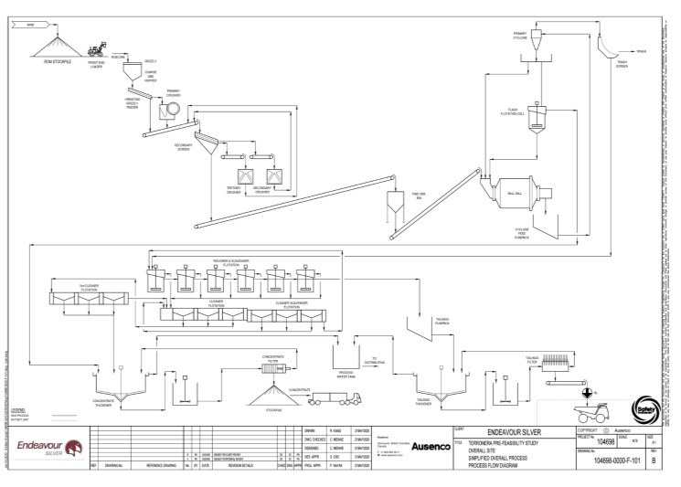
Source: Ausenco, June 2020
Figure 17-1 Overall Process Flow Sheet
17.2 Process Plant Description
The run-of mine (ROM) material will be transported to a coarse material storage patio with haul trucks. The crushing circuit is designed to process 1,600 dry tpd in 16 hours of operation. The beneficiation plant will operate continuously 365 days per annum. The beneficiation plant availability is assumed to be 92%. The bulk density of the ROM material is anticipated to be 2.61 t/m3 with average moisture content of 4%. The beneficiation plant will produce a precious metal-bearing concentrate as final product.
The processing methodology selected consists of the following processing circuits:
• Stock pile (2,000 t capacity)
• Crushing plant (three stage – closed circuit – 1,600 tpd capacity)
• Fine ore storage (1,600 t capacity)
• Primary grinding (1,600 tpd capacity)
• Flotation (1,600 tpd capacity)
• Flash flotation
• Roughers
• First and second cleaners.
• Final concentrate sedimentation and filtration (1,600 tpd capacity)
• Final concentrate storage and shipping (1,600 tpd capacity)
• Tailings sedimentation (1,600 tpd capacity)
• Reclaimed and fresh water systems
• Dry tailings filter plant
• Dry stack TSF.
The overall plant layout diagram of the proposed beneficiation plant is shown in Figure 17-2.
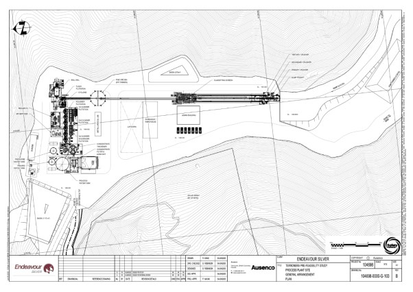
Source: Ausenco, June 2020
Figure 17-2 Overall Process Flow Sheet
17.2.1 Process Design Criteria
Key process design criteria for the process plant are listed in Table 17-1.
Table 17-1 Key Process Design Criteria for the Mill
Design Parameter | Units | Value |
Plant Throughput | t/d | 1600 |
Gold Head Grade | g/t | 2.1 |
Silver Head Grade | g/t | 204 |
Crushing Availability | % | 65 |
Mill Availability | % | 92 |
Bond Crusher Work Index (CWi) | kWh/t | 18.0 |
Bond Ball Mill Work Index (BWi) | kWh/t | 17.2 |
Bond Rod Mill Work Index (RWi) | kWh/t | 17.3 |
Axb | – | 38.9 |
Abrasion Index (Ai) | g | 0.50 |
Material Specific Gravity | t/m3 | 2.61 |
Moisture | % | 4 |
Silver Recovery | % | 84.0 |
Gold Recovery | % | 83.1 |
ROM F100 | mm | 500 |
Primary Cyclone P80 | µm | 70 |
Table 17-2 summarizes the list of major equipment at the Terronera mill.
Table 17-2 Major Equipment at the Terronera Process Mill
Description | Specification |
Fine Ore Bin | 870 t, 12 hours of live storage |
Primary Crusher | C106 crusher |
Secondary Crusher | HP200 or equiv – std head coarse liners |
Tertiary Crusher | HP200 or equiv – short head medium liners |
Ball Mill | 4.57m dia x 5.94 EGL @ 2.0MW |
Rougher Flotation Cell No.1 | Used 5x 30m3 cells from El Cubo |
Rougher Flotation Cell No.2 | Used 5x 30m3 cells from El Cubo |
Rougher Flotation Cell No.3 | Used 5x 30m3 cells from El Cubo |
Rougher Flotation Cell No.4 | Used 5x 30m3 cells from El Cubo |
Rougher Flotation Cell No.5 | Used 5x 30m3 cells from El Cubo |
Cleaner Flotation Cell No.1 | 3m3 rectangular cells (OK-3 in the OK-R series) |
Cleaner Flotation Cell No.2 | 3m3 rectangular cells (OK-3 in the OK-R series) |
Cleaner Flotation Cell No.3 | 3m3 rectangular cells (OK-3 in the OK-R series) |
Scavenger Flotation Cell No.1 | 1.5m3 rectangular cells (OK-1.5 in the OK-R series) |
Scavenger Flotation Cell No.2 | 1.5m3 rectangular cells (OK-1.5 in the OK-R series) |
Scavenger Flotation Cell No.3 | 1.5m3 rectangular cells (OK-1.5 in the OK-R series) |
Concentrate Thickener | Used 8m dia thickener from El Cubo |
Tailings Thickener | 22m diameter |
Concentrate Filter | 1000mm x 1000mm, horizontal plate and frame |
Tailings Filter Press | CX12-204 ceramic disc filter |
17.2.2 Crushing and Stockpiling
The crushing circuit will comprise a 24 t dump ore pocket fitted with a stationary grizzly with a 12 inch by 12 inch opening. The grizzly oversize will be broken with a hydraulic breaker. A grizzly feeder will send the ore to a primary jaw crusher to reduce the material to minus 70 mm. The crushed material and the dust fines from the feeder will be transported to subsequent stages of screening and secondary crushing in closed circuit to further reduce the material to minus 10 mm. Conveyor belts will be used to transport the intermediate and fine crushed materials throughout the entire crushing circuit. The crushing circuit design provides weigh scales, a crushed ore sampling system and magnetic separators to protect the cone crusher from iron coming from underground mining operations. The finely crushed product will be transported to a fine ore bin with 870 t live capacity.
17.2.3 Grinding Circuit
The grinding circuit design consists of a single stage primary ball mill. The ores from the Terronera deposit have been classified as hard with an average BWi of 17.3 kWh/t. Optimization of the grinding circuit design will be necessary to ensure that the specified target particle size will be achieved during normal plant operation.
A variable speed belt feeder will transport the crushed material from the fine ore bin to the primary ball mill. The material will be ground to 80% minus 70 μm in closed circuit with a battery of cyclones. Some flotation collector will be added into the ball mill discharge to allow for conditioning. Cyclone overflow at approximately 35% solids will be sent to a trash screen for removal of debris. After trash removal the clean slurry will be directed to the flotation process.
17.2.4 Flash Flotation
The flash flotation cell will be installed in the grinding circuit area. This cell will be fed with a portion of the cyclone underflow slurry. Dilution water will be added to achieve an optimal density. The flash flotation tail product will be directed to the mill feed box. The flash flotation concentrate will be sent directly to the final concentrate thickener.
17.2.5 Flotation and Concentrate Thickening
The flotation circuit will consist of banks of rougher cells to achieve maximum precious metal recovery. The rougher concentrates will be sent to the cleaning circuit to achieve the target gold and silver grade in the final concentrate. The first cleaner tailing product will be sent to the first cleaner scavengers. The cleaner scavenger tailings will be returned to the head of rougher flotation. The cleaner concentrate will be sent to the second cleaners and cleaner scavenger concentrate will report to the head end of the first cleaners.
The second cleaner tailings will be sent to the head of the first cleaners, while the concentrate will be sent to the concentrate thickener. Final concentrate will be filtered and the filter cake with moisture of 8% will be stored and air dried in a warehouse prior to shipment. Each concentrate shipment will be sampled and analyzed for precious metal and moisture contents. Impurities present in the concentrate will be quantified and evaluated prior to shipment.
17.2.6 Tailings Thickening
Rougher flotation tails will be sent to a tailings thickener. The higher density slurry produced will be filtered using one disk filter. The filter cake produced will be stockpiled at the dry tailings filter plant prior to sending the solids to the dry stack TSF. After sedimentation and filtration, the flotation tailings will be transported to the TSF by means of trucks. The filtered tailings will be placed in a stockpile and compacted. Front-end loaders and compaction equipment will be used to load, spread and compact the tailing material as required in the TSF.
Advantages of a dry stack tailings system include the following:
• Water reclaim maximization
• No embankment needed
• Minimal area required for placement
• Improved drainage control
• Lower reclamation cost.
17.2.7 Reagent Handling and Storage
The reagents to be used in flotation of sulphide mineralization associated with precious metals present at Terronera are outlined in Table 17-3.
Table 17-3 Reagents and Dosage
Reagent | Dosage (g/t) |
Collector PAX – Xanthate | 135 |
Frother F – 65 (MIBC) | 77 |
Flocculant SNF AN9135H | 30 |
Concentrate will be stored in a six-day capacity shed, from where it will be loaded onto trucks using a front-end loader. The trucks will transport concentrate to the market for ultimate refining at a third-party, toll facility. The third-party refining facility has not been confirmed as part of the UPFS, thus a nominal concentrate transportation distance of 50 km has been assumed, which is sufficient to deliver the concentrate to the port of Puerto Vallarta, at a minimum, for shipping as required.
17.2.8 Power Requirements
Electrical power will be supplied to the plant by way of a 4.5 km, 13.8 kV power line, supplied from an onsite power generation plant. The process plant power consumption was derived from the average power utilization of each motor included in the electrical load list for the process plant. An additional nominal consumption for the mining operations, ancillary buildings and miscellaneous users was applied to determine the total power requirement of 4.07 MW, with a peak requirement of 4.85 MW. Annual power consumption is estimated at slightly more than 30 GWh. Table 17-4 summarizes the total forecast power demand.
Table 17-4 1,600 tpd Power Demand (kW)
Equipment | Power (kW) |
Mine | 1,331 |
Process & Filter Plants | 3,252 |
All Other Facilities | 267 |
Total | 4,850 |
Note: Figures may not sum due to rounding.
17.2.9 Water Requirements
The water system for Terronera will consist of two separate systems:
• Fresh/fire water
• Reclaimed water
The bulk of the water requirements for the Terronera mill will be met with recycled water, recovered from the tailings filtration process. It has been assumed that there will be sufficient mine water from the underground operations to supply the fresh (or make up) water to the process facilities. A geohydrology study conducted in April 2020 (Gixtoh, 2020) indicated presence of shallow ground water at the mine site which would meet the plant water requirement. The estimated fresh water make-up requirement of approximately 15.6 m3/h, is equivalent to approximately 0.14 t of fresh/fire water per tonne of ore processed.
Water from the mine will be pumped to a fresh/fire water tank. Fresh/fire water will be pumped to the following process areas:
• Make-up to reclaim water tank
• Potable water
• Pumps gland water seals
• Reagent mixing
• Water trucks tank (dust abatement)
The reclaim water tank will distribute water by means of a pump to maintain appropriate pressure throughout the following processing circuits:
• Grinding
• Classification (dilution water)
• Flotation (launder water)
The effluent water is planned for minimal treatment and will be collected in settling ponds before discharging out. Hence, a water treatment plant is not considered in the current design.
18 Project Infrastructure
18.1 Existing Infrastructure
A public access road connects Puerto Vallarta with the local communities and the Terronera Project site area. The regional power needs are served by the State-owned Comisión Federal de Electricidad (Federal Electricity Commission or CFE in the Spanish acronym), which has a 23 kV power line that runs through the Terronera Project area. However, the UPFS assumes that electric power will be supplied by liquefied natural gas generators and solar power plant located on site. There is no other existing infrastructure on the Project site.
18.2 Proposed Infrastructure
The major project infrastructure is shown on Figure 18-1.
18.3 Process Plant
The process plant design is discussed in Section 17.
18.4 Tailings Filter Plant
The filter plant will take the flotation tailing product from the process plant and deposit it into sedimentation tanks. From there the sediment will be filtered by ceramic filters and pressed into a dry tailings material which will be conveyed to a stockpile. Trucks will then transport the dry tailings material to the dry stack TSF.
Source: Ausenco, 2020
Coordinate system: WGS 84 / UTM Zone 13Q
Figure 18-1 Map of Proposed Major Project Infrastructure
18.5 Temporary Waste Rock Storage Facilities
Temporary WRSFs will be constructed in the vicinity of the Terronera and La Luz portals. These WRSFs will vary in size throughout the LOM, reaching a maximum capacity of approximately 0.5 Mt for the La Luz area, and 1.88 Mt for the Terronera area. All rock material will be transported to the stockpiles in 12 m3 capacity trucks. The waste rock will be disposed and graded with a dozer at a slope ratio of 1.5H:1V to ensure physical stability during the temporary operation of the WRSFs. For both storage areas, the waste will eventually be returned to the mine as backfill. Where possible during the mine life, waste will be trucked directly to active levels to be used as unconsolidated backfill to limit haulage costs to the surface. The location of the temporary WRSFs in relation to the overall project facilities is shown in Figure 18-1.
The rocks will be up to 1m in size and preliminary geotechnical studies determined the maximum safe slope. Hydrological studies were used as a basis for designing the WRSF drainage systems. For the purposes of the UPFS, preliminary designs were prepared for both stockpiles.
18.6 Ancillary Buildings
Ancillary buildings necessary to support the Terronera Project include the following: administration building, warehouse/maintenance workshop, mine portal trailer for tagin-tagout, truckshop, first aid station, main gatehouse, fuel station, explosives storage facility, and metallurgical laboratory.
18.7 Camp Facilities
A construction camp will be established near the site to provide accommodation, meals, and ancillary services for construction and operations personnel. The construction camp will be built in a way such that the same camp can be transformed and used as a permanent camp when the mine operations start. The camp is designed for a peak capacity of 400 personnel. Due to the close proximity of the town of San Sebastian to the mines, it is expected that many employees and contractors will reside in the town.
18.8 Internal Haul Roads and Mine Access Infrastructure
The Terronera Project will include accesses that will be developed from existing public roads and minesite-specific haul and access roads to be used only by Project equipment and mine personnel. The site currently has roads that will be widened and upgraded. A portion of the Terronera construction phase work will includes improving those sections of the main community road between Los Pinos and San Sebastian that the mine will use during the operations phase. Small sections of the roads within the mine site will be developed.
Access from existing public roads will be used to connect the mine sites to external access and to connect the mine portal platform area to the process plant. These access ways will accommodate light-duty vehicles and heavy-duty traffic including dump trucks, semi-tractor trailers, and construction machinery. The proposed mine surface facilities layout was included in Figure 18-1.
Haul and access roads that will be used to transport personnel, equipment, rock and earth material haulage, and tailings between the process plant and the TSF will be developed on land either owned or leased by Endeavour Silver.
18.9 Power Supply and Distribution
Electrical power in the region is provided by CFE which operates the national grid in Mexico. An existing 23 kV power line runs from the Tamarind substation in Ixtapa (near Puerto Vallarta), across the Terronera Project; however, this line has no excess power available for use by Endeavour Silver.
The total estimated power requirement is a peak of 4.85 MW at the plant site, with an additional 1 MW required at the accommodations camp site.
A local power generation facility with a combination of liquified natural gas and solar power will be installed at the plant site.
The accommodations camp will be located in a separate area served with utility power, and it is planned to be powered from the utility powerline.
18.10 Water Supply and Distribution
The fresh/fire water tank will collect and store excess water from the mine or from ground water. All of the mill facilities fresh water requirements will be made up from mine water and/or collected run off.
The fresh/fire water tank will have a live volume of 50 m3, and will be situated in the process plant next to the concentrate thickener. This tank water will be the main supply of process water and potable water for the site.
Potable water will be treated before consumption.
18.11 Waste Management
All domestic waste will be treated in sewage treatment facilities.
18.12 Surface Water Control
Surface contact water generated from the process plant and waste rock dump areas will be collected, using three contact water ponds, to allow for sediments to settle and for water quality monitoring before discharging to the environment.
A surface contact water and seepage pond will be located below the TSF, and will collect contact water from surface and subsurface drainage from the TSF. Contact water quality will be monitored to determine if it meets allowable limits so it can be discharged.
18.13 Communications
The site will be serviced by a fiber optic telecommunications line. A telephone system with extension lines will connect all parts of the mine, process plant, and ancillary buildings. Mobile communications comprising cell phones and radio sets will be available for operating staff.
19 Market Studies and Contracts
19.1 Market Studies
Endeavour Silver produces a silver concentrate from its other current operating mines, which is then shipped to third parties for further refining before being sold. To a large extent, silver concentrate is sold at the spot price.
Endeavour Silver’s hedge policy does not allow the company to enter into long term hedge contracts or forward sales. As of July 14th, 2020 Endeavour Silver has not conducted any market studies, as gold and silver are commodities widely traded in world markets.
Due to the size of the bullion market and the above-ground inventory of bullion, Endeavour Silver’s activities will not influence gold or silver prices.
19.2 Commodity Prices
Table 19-1 summarizes the annual high, low, and average London PM gold and silver prices per ounce from 2000 to 2020 (May).
Table 19-1 Annual High, Low, and Average London PM Fix for Gold and Silver from 2000 to 2020
Year | Gold Price (US$/oz) | Silver Price (US$/oz) | ||||
High | Low | Average | High | Low | Average | |
2000 | 314 | 264 | 279 | 5.45 | 4.57 | 4.95 |
2001 | 293 | 256 | 271 | 4.82 | 4.07 | 4.37 |
2002 | 350 | 277 | 310 | 5.10 | 4.24 | 4.60 |
2003 | 417 | 320 | 364 | 5.97 | 4.37 | 4.88 |
2004 | 453 | 375 | 410 | 8.29 | 5.50 | 6.66 |
2005 | 537 | 412 | 445 | 9.23 | 6.39 | 7.31 |
2006 | 720 | 513 | 604 | 14.94 | 8.83 | 11.55 |
2007 | 845 | 604 | 697 | 15.82 | 11.67 | 13.38 |
2008 | 1,012 | 711 | 872 | 20.92 | 8.88 | 14.99 |
2009 | 1,212 | 810 | 973 | 19.18 | 10.51 | 14.67 |
2010 | 1,418 | 1,057 | 1,226 | 30.70 | 15.14 | 20.19 |
2011 | 1,898 | 1,326 | 1,571 | 48.70 | 26.16 | 35.12 |
2012 | 1,792 | 1,541 | 1,669 | 37.23 | 26.67 | 31.15 |
2013 | 1,693 | 1,196 | 1,411 | 32.23 | 5.08 | 21.26 |
2014 | 1,376 | 1,146 | 1,266 | 22.05 | 15.28 | 19.08 |
2015 | 1,302 | 1,052 | 1,160 | 18.23 | 13.71 | 15.68 |
2016 | 1,369 | 1,062 | 1,249 | 20.71 | 13.58 | 17.21 |
2017 | 1,347 | 1,156 | 1,258 | 18.56 | 15.22 | 17.05 |
2018 | 1,355 | 1,178 | 1,269 | 17.52 | 13.97 | 15.71 |
2019 | 1,546 | 1,270 | 1,393 | 19.31 | 14.38 | 16.21 |
2020 May | 1,748 | 1,474 | 1,634 | 18.78 | 12.01 | 16.53 |
Over the period from 2000 to 2020, world silver and gold prices have increased significantly. This had a favourable impact on revenue from production of most of the world’s precious metal mines.
The Mineral Resource estimate uses commodity prices of US$1,275/oz Au and US$17.50/oz Ag.
The Mineral Reserve estimate uses commodity prices of US$1,325/oz Au and US$17.00/oz Ag.
The financial model uses prices of US$1,419/oz Au and US$15.97/oz Ag.
19.3 Contracts
In its current operations, Endeavour Silver has no contracts or agreements for mining, smelting, refining, transportation, handling or sales that are outside normal or generally accepted practices within the mining industry. No contracts or agreements are in place for the Terronera Project.
In addition to its own workforces, Endeavour Silver has a number of contract mining companies working at its three operating mines and is evaluating the possibility of using contract miners at Terronera.
The refining costs, payability and concentrate grade requirements assumed in the economic analysis, summarized in Table 19-2 are based on Endeavour Silver’s other operating assets in Mexico.
Table 19-2 Market Factors Assumed in Economic Analysis
Description | Value |
Payability Factor (Ag and Au) | 97.5% |
Ag Concentrate Grade Requirement | 4428 g/t |
Treatment Charges | $175/dmt |
Refining Charges (Ag) | $0.5/oz |
Refining Charges (Au) | $5/oz |
Moisture Content | 8% |
20 Environmental Studies, Permitting and Social or Community Impact
20.1 Permitting Basis
The Terronera Project submitted, in December 2013, a Manifest of Environmental Impact (« MIA »), the Mexico Federal Government’s equivalent to a Canadian Environmental Assessment, to the Mexican environmental permitting authority known as SEMARNAT (Secretaria de Medio Ambiente y Recursos Naturales). A SEMARNAT permit for a 500 tpd Terronera Project was issued in October 2014. Prior to the December 2013 MIA application, Endeavour Silver was issued an exploration MIA and certain associated SEMARNAT permits specific to the exploration phase for the project.
In February, 2017 a modified MIA application was issued by SEMARNAT to expand the proposed process rate to up to 1,500 tpd and to establish that the tailings storage facility would be developed as a filtered tailings storage facility. Another modification will be required to the existing MIA to address the current production rate of 1,600 tpd. However, based on information provided by EDR’s local environmental consultant (Ruben Padilla), this modification process should be relatively simple and expedient.
The Terronera Project process plant feed will be processed on site by flotation. The processing agents will not include cyanide or any other substance considered by the Mexican environmental regulators as a highly dangerous substance and will be limited principally to agents such as coagulants, surfactants, and flocculants that facilitate the process of « floating » the silver and gold that are introduced to the process circuit in the processed material.
These flotation agents are typically relatively inert. Majority of reagent chemicals are captured in very fine (80% sub #200 gradation) tailings waste that is stored, and thus contained, within the filtered tailings storage facility (« TSF »). Any potential seepage from this and other storage facilities will be monitored and treated to achieve constant on-site reagent containment.
Tailings that do not include cyanide processed ore are covered by regulations that are unique and separate in the SEMARNAT permitting system from those for cyanide leaching ore processing. The flotation regulations are more appropriate for the hydrological, seismic, TSF geometry, and natural terrain conditions at the Terronera Project than the regulations applicable to mines that require cyanide process permits for their TSF entitlement requirements.
The flow chart for Mexico mine permitting is shown in Figure 20-1.
Source: Endeavour Silver (2018)
Figure 20-1 Environmental Permitting Steps for Mining Projects in Mexico
The status of the Terronera Project as of the effective date of this UPFS per the Federal, State, and Regional/Municipal governing bodies in Mexico is as listed in Table 20-1.
Table 20-1 Environmental Permits Required for the Terronera Project
Mining Stage | Agency / Permit | Submittal Documentation | Required per Endeavour Silver / Submittal Date if Issued | Comments Observations |
Exploration | SEMARNAT / NORMA de Ley General | Exploration MIA | 31 Oct. 2011 | Permit Issued to Minera Plata Adelante – extended for 24 months on 20 January 2017 |
Exploration ETJ | 19 Jan. 2013 | Permit Issued to Minera Plata Adelante for the Terronera Vein exploration – Diligence ongoing for additional exploration permissions for the La Luz and Espinos Veins. | ||
Construction | Local Municipality: | Application | Yes | Will be requested from the local municipality after the precedent permits have been granted. |
SEMARNAT: | Application | n/a |
| |
INAH: | Survey | n/a | No evidence of archeological sites currently exists for Terronera Project. | |
SEDENA, Local Municipality and State Governments: | Application and Endorsement Letter – All submittals occur after SEMARNAT authorizations are issued. | Yes | The SEMARNAT Change of Land Use permit is issued prior to presentation of SEDENA (Federal), State, and Local applications. | |
SEMARNAT: | Environmental Impact Manifesto (MIA) |
Yes | 500 tpd MIA submitted Dec 2013 and granted in Oct 2014. 1,500 tpd MIA modification was authorized by SEMARNAT on 23 Feb 2017. The 1000/2000 tpd MIA modification has not been submitted for SEMARNAT review as of the date of this report. |
CONAGUA: | Various Documents | Yes. It has been confirmed that the TSF basin natural drainage flow exceeds the threshold of 2 m width and 0.75 m depth in a 5 year storm event. | The concession was granted in January 2019 for a period of 30 years. | |
CONAGUA: | Various Documents | Yes | In-progress. Hydrological studies are being developed as part of the environmental impact statement | |
CONAGUA: | Application Form Supported by Technical Documents. | Yes | Application CNA 02-002 to construct the TSF in the Federal Zone has been approved by CONAGUA and is valid until August 2021. | |
CONAGUA: | n/a | n/a | They are considered within the construction permit mentioned above. | |
SEMARNAT: | Risk Analysis Study (ER) | Risk Analysis Study is typically not required when cyanide (NaCN) is not used in the processing circuit. Terronera will be a flotation circuit thus excluding the use of NaCN. | The risk level of the project will be assessed in the Feasibility Stage of the Project, when a thorough list of hazardous substances and their amount to be stored on-site is available. | |
SEMARNAT: | Unified Technical Document (DTU) | n/a | Once the MIA has been issued and the ETJ is in process the DTU is not typically required. |
Operation | CONAGUA: | Various Documents | Yes | Documents will be submitted to CONAGUA after completion of the Feasibility Study and prior to Terronera operation activities. |
MUNICIPIAL: | Various Documents | Yes | Provides an Environmental Registration (ER) number for the mine. Requested by Minera Plata Adelante prior to the time of mine startup. | |
SEMARNAT: | Const. Phase Risk Analysis Covers this Requirement | Included in ER | Included in Risk Analysis Documentation (ER shown above) | |
MUNICIPAL: | Various Documents | Yes | This document will register prior to mine start-up the use of certain chemicals, oils, and slag materials. | |
SEMARNAT: LGPGIR | Management Plan that complies with the Mexican Law for Integral Prevention and Management of Waste | Yes | Management plan will be generated & submitted to SEMARNAT by Minera Plata Adelante per the requirements of LGPGIR | |
SEMARNAT: | Management Plan that Complies with NOM-157 | Yes | Management plan will be generated & submitted to SEMARNAT by Minera Plata Adelante per the requirements of NOM-157-SEMARNAT-2009 | |
SEMARNAT: Environmental license LGEEPA, regulations on air pollution | Various Documents to comply with the General Law of Ecological Balance and Environmental Protection | Yes | License will be generated & submitted to SEMARNAT by Minera Plata Adelante per the requirements of LGEPA | |
Closure | SEMARNAT: | Closure Plan that Complies with NOM141 Sect. 4.17 and with NOM-157, Sect. 5.6 | Yes | Plan should be submitted to SEMARNAT w/ 1000/2000 tpd MIA application, updated during the mine operation phase, and finalized prior to closure of mine. |
20.2 Existing Site Conditions
20.2.1 Baseline Studies
Certain environmental baseline studies were performed in support of the MIA, and included:
• Meteorology
• Air quality
• Climatology
• Soil erosion and contamination
• Surface and subsurface hydrology
• Flora and fauna;
• Cultural, historical, archeological resources.
20.2.2 Topography
The Terronera Project is located in a mountainous region of Western Mexico with elevations ranging from sea level at the Pacific coast to 2,850 m in the highest elevation in the San Sebastian region of the Sierra Madre Occidental mountain range. Elevations range from 1,160 m to 1,800 m within the Terronera Project footprint.
The initial topographical and geographical mapping basis for the development planning for the Terronera Project was captured by satellite photogrammetry on March 1, 2012 by Photosat Satellite and GIS Data Consultant of Vancouver, Canada. An update to this topographical mapping, exclusive to the tailings facility area, was performed by COTOSI via a drone-aerial survey. The topographic resolution for this data generated one-meter contours. Because the project area has remained relatively undisturbed since the date of this satellite capture the image and contour data remains current and relevant for the basis of this PFS.
20.2.3 Meteorology – Air Quality
The climate type reported for the project site is subtropical with the rainy season occurring from June to September, with July typically being the wettest month. Data from the closest meteorological station (San Sebastián del Oeste), show the average annual precipitation as 1.35m. The maximum mean air temperature is 25.6° C and the minimum mean is 11.7° C. Prevailing winds in the area are from the southwest.
No existing data on air quality is available for the project area. Existing unpaved road traffic may be the main source of dust but, in general, the area is considered to have good air quality as a rural and relatively undeveloped area.
20.2.4 Soil
The predominant type of soil in the Mondeño is known as regosol per the agricultural soils nomenclature. Soils of this type generally result from the relatively recent formation of non-alluvial substrates and are located in areas with strong erosion causing continuous soil creation from the weathering of the host rock.
The regosol soils in the Terronera area are of silt-clay texture of high plasticity (USCS type CH), clayey sands (SC), highly compressible silts (MH) and silty sands (SM) with a density range of 1,359 to 1,929 kg/m3 and an in-situ moisture range of 6% to 37% within the sampling from the seventeen open pit tests performed by Wood in the Mondeño basin.
20.2.5 Geotechnical and Seismic Studies
Geotechnical investigations including subsurface hollow stem auger drilling, standard penetration testing (SPT), and soil/core samples, test pits, and, as appropriate, permeability testing, occurred utilizing various drilling and coring subcontractors and were supervised and logged by Wood geotechnical engineers between December, 2015 and October, 2016 for the preliminary design phase for the tailings, soils, and waste rock storage facilities.
Wood generated, in November 2014, and then updated in October 2016, a Deterministic Seismic Hazard Assessment for the Terronera Project site. The report’s findings identify the seismic influence of the Jalisco block and Rivera and Cocos tectonic plates at the tectonic subduction zone approximately 175 km west of the project site along the margin of the Pacific coast. Three earthquakes of 8.0 Richter magnitude or greater have occurred within 320 km of the site since 1930. The deterministic weighted mean un-attenuated horizontal acceleration for the site was determined in the Wood study to be 0.48 g. For this reason, Wood has recommended that tailings be stored in a structurally placed and densified filtered tailings configuration that meets physical stability requirements.
20.2.6 Hydrology
According to the hydrological classification system used by the Mexico Federal water commission, CONAGUA, the Terronera Project area is located within the administrative hydrologic region #3, « Pacifico Norte ».
If the flow of stormwater, in the drainage area that the proposed mine facilities are located within can flow during a five-year return period intensity with a stream width of ≥two meters and a depth of ≥0.75 meters then a permit to construct facilities in what is regarded as « Federal Waters », or « Federal Zone » can be required by CONAGUA. The several principal drainages in the Mondeño have been determined by hydrologic and hydraulic analysis to exceed these CONAGUA Federal Zone flow thresholds. For this reason, the Terronera filtered tailings deposit design and operational procedure was established by Wood for this UPFS to comply with the CONAGUA Federal Zone regulations.
Hidrologia e Hidraulica de Mexico generated, in May 2016, a Precipitation Analysis Study for the Terronera Project. The study evaluated precipitation data from three meteorological data stations within 36 km of the project, including the San Sebastian station about four km from the site. The return period data necessary for pending hydraulic sizing and design configuration of Terronera site drainage infrastructure is shown in Table 20-2.
Table 20-2 Return Period Storm Event Precipitation
Return Period Size | 24 Hour Precipitation (mm) |
2 years | 79 |
5 years | 103 |
10 years | 120 |
20 years | 138 |
50 years | 157 |
100 years | 171 |
500 years | 205 |
1,000 years | 221 |
5,000 years | 260 |
10,000 years | 277 |
20.2.7 Watershed – Surface Hydrology
The Terronera Project is located in the watershed Rio Ameca – Ixtapa. This watershed covers an area of 3,160 km2. The watershed western boundary occurs at the Pacific Ocean. The sub-basin including the Terronera Project is the San Sebastian drainage which captures approximately 84,700 hectares of drainage area.
20.2.8 Sub-Surface Hydrology
The Terronera Project is located above the aquifer Mixtlán, specifically in the northwestern quadrant of the aquifer.
Endeavour Silver is anticipating that the Terronera Project will use excess water pumped from the mine tunnels and recovered from the tailings filter plant for 100% of the operations water demand. The beneficial use of processing ore using water from underground workings is established in Article 19 of Chapter 3 of the Mexican Mining Law.
Under water law in Mexico, mining process water cannot be returned to the surface or subsurface basins without treatment in accordance with SEMARNAT NOM-001, Limits of Contaminants in the Discharges of Wastewaters into the Mexican National Waters and Resources.
20.2.9 Land Use
The communities in the project area have been organized since the early 1900’s into various ejidos, or community groups, which distribute and share agricultural and other lands for the benefit of the ejido member families. The Terronera Project has completed negotiations with various ejido members for leased surface rights of certain parcels of land needed for the location of the tailings and waste rock storage facilities. The aggregate limit of these parcels is identified on Figure 20-2 as the dashed magenta line labeled as the TSF surface area boundary.
The predominant use of land at the site project is forestry, pastureland, and subsistence agriculture. The SEMARNAT default land use is known in Spanish as « forestal », or forest in English.
A network of unpaved roads exists for transportation between communities and ranches. The Terronera Project has used these roads for exploration phase access. A portion of the Terronera construction phase work includes improving those portions of the main community road between Los Pinos and San Sebastian which the mine will utilize during the operations phase of the project.
20.2.10 Vegetation and Ecosystems
A study area inventory was performed by Ing. Roberto Trujillo of the Consultoría Forestal y Ambiental of Durango, DGO, Mexico for the Terronera Project. The results are included in the MIA report submitted to SEMARNAT in February 2017, for a 1,500 tpd Terronera Mine and process plant. As mentioned in Section 20.3, an additional modification will be required to the existing MIA to address the current production rate of 1,600 tpd.
The Trujillo study identifies fauna and flora as a baseline condition for the project area and recommends certain actions to minimize the environmental impact of the proposed Terronera Project.
20.3 Dry-Stack Tailings Storage Facility
20.3.1 Design Considerations
The TSF will store filtered tailings, or « drystack » tailings, to minimize downstream contamination risk and to maximize geotechnical stability in the seismically active coastal area of western Mexico.
The TSF design will accommodate approximately 3.9 million m3 (5.8 million tonnes) of compacted filtered tailings over a 10-year mine life based upon an initial process rate of 1269 tpd during the first year and approximately 1,600 tpd in subsequent years. The capital costs for the TSF were prepared by Wood and are included in Section 21.
The layout of the proposed TSF is shown in Figure 20-2.
Source: Wood (2020)
Coordinate system: WGS 84 / UTM Zone 13Q
Figure 20-2 Map of the TSF Layout
20.3.2 TSF Location and Geometry
The location of the TSF in relation to the overall project facilities is shown in Figure 18-1. The TSF is located in a valley approximately 1 km northwest of the process plant. The current footprint of the TSF occupies a footprint area of approximately 89,760 m2.
The TSF is designed to have an overall downstream slope of 2.8 Height (H) to 1 Vertical (V) with interim benches of 6 m width and slopes 10 m in height at 2.2H:1V slope. Below the TSF to the northwest, there is a proposed storm water collection pond to collect, monitor, treat, and release storm water from the TSF surface area and any subgrade water that is not qualified to be released downstream.
Upstream drainage will be captured in cutoff ditches constructed immediately above the TSF upstream perimeter and routed to the natural drainage course below the TSF as non-contact water.
20.3.3 TSF Operating Methodology
Filtered tailings will be placed and compacted in lifts of approximately 30 cm to a design target density of 1.76 MT/m3 at an optimal moisture content of approximately 18%. It is proposed that the TSF be constructed and reclaimed concurrently with erosion protection, re-vegetation, and drainage structures once the TSF toe dam and its initial bench and slope are completed.
20.3.4 Tailings Transport and Deposition
The proposed TSF will be constructed with filter tailings produced by a filter plant that is located uphill from the TSF. Filter tailings will be transported to the TSF area by either 12 m3 haul trucks that will transport the filtered tailings approximately one-half km along a proposed newly constructed haul road. A dry tailings staging area will feed the dry tailings haul trucks at the filter plant site.
At the TSF, the tailings will be truck end-dumped or radial conveyor-placed, spread, and compacted by a series of mid-size dozers, motor grader(s), and vibratory roller compactors.
20.4 Terronera and La Luz Waste Rock Dumps
Temporary waste rock dumps will be constructed in the vicinity of the Terronera and La Luz portals. These waste dumps will vary in size throughout the life of mine, reaching a maximum capacity of approximately 0.5 million tonnes for La Luz area, and 1.88 million tonnes for the Terronera area. The location of the temporary waste dumps in relation to the overall project facilities is shown in Figure 20-3.
20.4.1 Terronera Temporary Waste Dump
The Terronera waste dump will be located southeast and uphill from the proposed Terronera portal, filling a small valley and a portion of an ephemeral creek that flows just north of the portal in a southeast-northwest direction (Figure 20-3). Waste rock transport will be by trucks from the Terronera portal so the temporary waste dump will be constructed from the bottom up starting with the installation of a culvert to allow the flow of the ephemeral creek and construction of the access road and contact water pond over the streambed.
Prior to waste rock placement, surface non-contact water diversion structures will be constructed upstream to reduce surface drainage as well as subdrains to handle sub-surface drainage. The waste rock will be placed with a dozer at a slope ratio of 2H:1V to ensure physical stability during the operation of the temporary facility.
Figure 20-3 Proposed Layout of the Terronera Temporary WRSF
20.4.2 La Luz Temporary WRSF
The La Luz waste dump will be located northwest and downhill from the proposed La Luz portal (Figure 20-3). Waste rock transport will also be by trucks from the La Luz portal, although waste rock disposal will be by end dumping from an existing access road just east of the portal.
Prior to waste rock placement, surface non-contact water diversion structures will be constructed upstream to reduce surface drainage as well as subdrains to handle sub-surface drainage. A small lined dike will be constructed downstream from the proposed waste dump footprint to collect contact water and reuse it in the underground mine or, if water quality allows it, discharge it into the surface stream. An access road will be constructed tying into an existing road to build the starter buttress which will provide physical stability to the temporary waste dump and reduce the rockfall distance caused by end dumping from the top of the hill. Following end dumping, waste rock will be rearranged and graded with a dozer at a slope ratio of 2H:1V to ensure physical stability during the operation of the temporary facility.
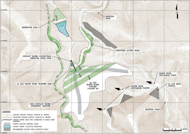
Figure 20-3 Proposed Layout of the La Luz Temporary Waste Dump
20.5 Environmental Considerations for Tailings Storage
20.5.1 Substances and Residues Used and Produced by the Ore Processing Operations
The reagents used in the process flotation operations are Ciba MF 155 or equivalent, MIBC and PAX sulphide collector.
The mine area will utilize a variety of oils, greases, and chemicals, and other reagents that will be identified, quantified, classified, and submitted for registration per NOM-052, 083, & 157 specific to the Mine Risk Analysis and Application for the Generation of Hazardous Wastes.
20.5.2 Geotechnical Characterization of the Starter Dam Structure and Filtered Tailings Storage
Subject to the requirements of NOM-157 – SEMARNAT 2009 Wood has performed testing on the waste rock to quantify acid generating, or potential acid generating waste rock. The tailings have also been sampled and tested for potential contaminants for the purpose of sizing/designing the TSF contact water management pond as shown at the toe of the tailings storage facility in Figure 20-2. Results to date indicate that tailings have low potential for acid generation, whereas the waste rock exhibit low to uncertain potential for acid generation.
No site investigation or geotechnical characterization of the materials in the waste rock dump areas has been conducted at this time. However, based on the available information from aerial photography and geological conditions in the vicinity of the Terronera and La Luz portals, the proposed waste dump sites appear suitable for temporary waste rock storage. On-site geotechnical and material characterization of these areas will need to be performed to further advance or confirm their current design.
20.5.3 Environmental Monitoring Program
The Terronera Project will be required to comply with the environmental regulations and standards in place in Mexico. The mining infrastructure and supporting facilities will need to be designed to minimize the impact to the natural environment.
Mexican law requires that an environmental program be implemented to monitor the surface and underground water, creek sediments, soil, air, vegetation and wildlife conditions. Wood has supported Endeavour Silver during the installation of four dual piezometer/water quality monitoring wells in the Mondeño basin as shown in Figure 20-4. Additional wells have been proposed by Wood at upstream and downstream locations of the TSF to verify groundwater quality once the TSF is operational.
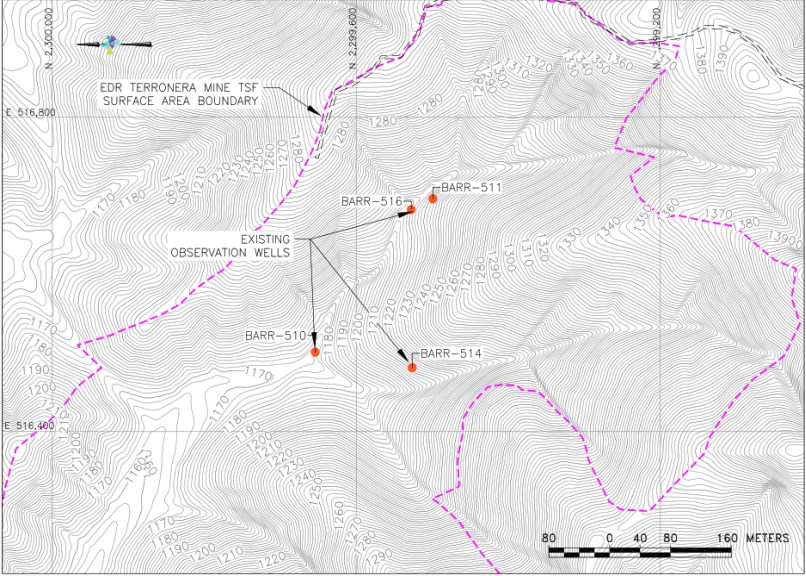
Source: Wood (2020) Coordinate system: WGS 84 / UTM Zone 13Q
Figure 20-4 Map of the Mondeño Tailings Storage Area Monitoring Well Locations
20.5.4 Surface Water Management
The Wood design components for the Terronera tailings management facilities are shown on Figure 18-1 and are listed as follows:
• The filtered tailings storage, or TSF, with a capacity of approximately 5.8 million tonnes of densified tailings material
• The process plant site
• The Terronera and La Luz underground mine portals and their respective temporary waste rock dumps
• Several mine roads connecting the town to the mine portals and the portals to the process plant
• A constructed haul road from the process plant to the filter plant. This road also provides the alignment for the raw tailings and filter plant extracted process water piping
• A constructed haul road from the filtered tailings plant to the active TSF platform
• A platform uphill from the TSF on which the filter plant will be located.
These features will interrupt natural drainage courses and will need to be designed to accommodate both typical stormflows and the 50-year design stormflows as stipulated in SEMARNAT NOM.141 Section 5.3.1. Because the TSF is located in a Federal Zone as designated by CONAGUA the non-contact diversion structures in association with the final footprint of the TSF will be sized to be able to successfully pass through the TSF the 10,000 year return period stormflow.
The constructed haul roads will utilize concrete, HDPE, and ADS plastic culverts sized according to NOM141 criteria to pass 50-year return period design storm flows. The TSF will use a combination of perimeter canals constructed above the facilities, subdrain rock and pipe systems beneath the storages, and, where feasible, culverts to route design storm flows through facilities as appropriate. Long culverts with minimal slope will be avoided in favour of open drainage structures so as to minimize culvert maintenance.
20.5.5 Mine Water Discharge
Mine water will be pumped to the surface and utilized as process water. Any process water excess will need to be water quality tested and can be discharged downstream if compliant with SEMARNAT NOM157 Section 5.4.2.4.1 mine waste discharge contamination limits, and certain applicable sections of NOM-001. If not compliant, it will need to be stored, treated, and tested to achieve compliant discharge.
20.5.6 Groundwater Management
The current process water demand estimate does not require the use of groundwater from the project aquifer Mixtlán.
Wood, as part of the permitting submittal to CONAGUA, conducted 2-D water infiltration modeling through the tailings dry stack and the native vadose zone that considered the tailings unsaturated pore water properties, the effects of drystack height or geometry as it grows over time, and the climatological conditions of the site (Wood, 2018). Based on the available site data and the projected drystack properties, it is anticipated that no liner would be required over the entire area of the TSF to prevent infiltration into the native ground, however, the TSF design includes the construction of a subdrain system in identified ephemeral and perennial spring areas at the bottom of the existing valley and the inclusion of a geomembrane both to prevent saturation of the overlying filtered tailings material and to separate contact from non-contact water at the base of the TSF.
20.5.7 Air Quality Management
SEMARNAT NOM-141, specific to tailings facilities, provides fairly general commentary on limiting fugitive dust contamination of surrounding communities, and of the need for mine perimeter particulate contamination monitoring.
20.5.8 Soil-Rock Management as Closure Capping Materials
In accordance with SEMARNAT regulations, during the stages of preparation, construction, operation, maintenance and closure/reclamation, actions must be taken to prevent soil erosion and contamination of native soils in the project area.
The Terronera TSF plan, as shown in Figure 18-1and Figure 20-2, demonstrates the geometry for the Mondeño filtered tailings deposit that will be generated by the processing of 5.56 M tonnes of ore as presented in this PFS. At more advanced stages of design documentation, Wood will recommend the storage and preservation on-site of dedicated topsoil and waste rock storages of sufficient volume to facilitate capping of the TSF to achieve long term erosion control, dust control, and to contain the filtered tailings storage within a stable surface cover mantle of soil-rock material that will minimize ongoing TSF management at the time of the implementation of the project reclamation and closure plan.
20.5.9 Solid Waste Disposal
Hazardous waste management criteria are established in SEMARNAT NOM-052; 2005 which describes the characteristics, process of identification, classification, and listing of hazardous waste.
Hazardous waste generated onsite will need to be loaded into containers that clearly identify the type of waste and placed in an appropriate disposal area for such waste.
20.6 Socio-Economic and Community Relations
The project is near the communities of San Sebastian del Oeste, Santiago de Pinos, and Los Reyes. These three relatively typical Mexican « pueblos » belong to the municipality of San Sebastian del Oeste, Jalisco. Per the Federal Mexican census of 2010, this municipality has 5,755 inhabitants.
Endeavour Silver is currently working under existing Mexican environmental laws, and as part of the MIA process, has engaged the community to inform them about the Project and encourage public participation as the Project progresses. To date, the local community is in favour of resource development and accepts the potential economic benefit, especially employment.
20.7 Cultural and Historical Resource Studies
According to the baseline cultural and historical resource studies, the Qualified Person is unaware of any cultural events or practices or any historical landmarks that would interfere with the development of the Terronera Project.
20.8 Archeological Artifacts and Studies
According to the baseline archaeological studies, the Qualified Person is unaware of any archaeological artifacts that would be impacted by the development of the Terronera Project.
20.9 Reclamation and Closure Activities
A Terronera closure and reclamation plan will be included in an amended MIA permit application, and ETJ support documentation, as outlined in the Construction Phase portion of Table 20-1.
Every three years during the active mine operation, and no less than three years prior to the closure of the mine, an updated closure plan should be presented to SEMARNAT for the Terronera Project.
At the end of the mine life, Endeavour Silver shall perform restoration activities on impacted areas ensuring the stability of disturbed areas. These efforts should be started to the extent possible during project operations and be completed within two years after the end of the mine operations.
20.9.1 Mine Surface Disturbance Closure Activities
20.9.1.1 Resurfacing and Vegetation
The Terronera Project above ground improvements will need to be dismantled and removed from the site. The resulting disturbed platforms and other surface areas will need to be covered with rock or stable soil fill as necessary to provide positive drainage conditions and then capped with topsoil from the mine topsoil storage generated during mine development. The topsoil capped areas will need to be re-vegetated to provide a permanent self-sustaining rehabilitation of the previously disturbed mine surface area.
20.9.1.2 Mine Runoff and TSF and Rock Storage Seepage Management
Any mine generated contact water seepage that does not qualify for release into the downstream environment will need to be managed as actively treated flows until such time as it can qualify for direct release per the discharge limits criteria of SEMARNAT NOM-001 Contaminant Discharge, NOM-157 Mine Discharge, and NOM-052 Hazardous Waste. As is typical of contemporary mine closures, the final mine closure will need to be a mine site with a condition of zero non-qualified release of runoff.
20.9.2 Underground Mine Infrastructure Closure Activities
All vent raises and portals that provide access to underground workings should be properly sealed to prohibit access to underground workings. Subsurface mine water that reaches the surface should be managed as surface runoff.
21 Capital and Operating Costs
21.1 Capital Cost
21.1.1 Summary
The study cost estimate has been divided into the following areas:
• Initial Capital, consisting of:
o Direct Costs
o Indirect Costs
o Owner Costs
o Contingency
• Sustaining Capital.
The estimate conforms to Class 4 guidelines as set out by AACE International for a PFS-level estimate with an accuracy range between -20% to +30%.
The estimate base date is June 22, 2020. Table 21-1 provides a summary of the estimate for overall initial capital cost. The estimate includes costs for mining, site preparation, process plant, dams, first fills, buildings, roadworks, and off-site infrastructure.
Table 21-1 Capital Cost Estimate Summary
WBS 1 | WBS Description | Cost (US$ 000’s) | % of Total |
1000 | Mining | 43.9 | 44.3% |
2000 | Tailings Management Facility | 3.4 | 3.4% |
3000 | Ore Crushing & Handling | 4.7 | 4.8% |
4000 | Mineral Processing Plant | 11.0 | 11.1% |
5000 | On-Site Infrastructure | 9.8 | 9.9% |
6000 | Off-Site Infrastructure | 0.0 | 0.0% |
| Total Direct Costs | 72.8 | 73.5% |
7000 | Project Indirects | 10.4 | 10.5% |
9000 | Owner Costs | 5.8 | 5.8% |
10000 | Contingency | 10.0 | 10.1% |
| Total Indirect Costs | 26.2 | 26.5% |
| Project Total | 99.1 | 100.0% |
The estimate is based on an engineering, procurement and construction management (EPCM) execution approach. The following parameters and qualifications were considered:
• Wherever suitable, used mechanical and electrical equipment from Endeavour Silver’s El Cubo mine is considered for the Terronera mill. A cost allowance has been included for internal repurchase of used equipment, relocation and reclamation. Since both operations are owned by Endeavour Silver, the company has agreed to the transfer of equipment from El Cubo to Terronera.
• No allowance has been made for exchange rate fluctuations
• There is no escalation added to the estimate
• A growth allowance was included
• Data for the estimates have been obtained from numerous sources, including:
o Mine schedules
o UPFS engineering design
o Topographical information obtained from the site survey
o Geotechnical investigations
o Budgetary equipment quotes
o Budgetary unit costs from local contractors for civil, concrete, steel, electrical, and mechanical works
o Data from similar recently completed studies and projects.
Ausenco engaged inspectors to physically inspect the availability and condition of the equipment at El Cubo mine. Prior to the visit, Ausenco reviewed the process flow diagram (PFD), mechanical equipment list and electrical equipment list of the equipment at El Cubo and identified the list of equipment that would be suitable for operation at Terronera. During the visit, the inspectors inspected every piece of equipment and confirmed the availability/non-availability, provided a report on the equipment condition, and identified equipment that was not suitable for reuse. Only that equipment, considered to be in good condition and able to be used with minimal refurbishment, has been considered in the current design. The cost of used equipment is estimated to be 20% of the new cost, and the transportation and rehabilitation costs were based on a study report provided by Endeavour Silver.
Major cost categories (permanent equipment, material purchase, installation, subcontracts, indirect costs, and Owner’s costs) were identified and analysed. A contingency percentage was allocated to each of these categories on a line-item basis based on the data accuracy . An overall contingency amount was derived in this fashion.
21.1.2 Exchange Rates
The estimate is prepared in US$. Pricing has been converted to US$ using exchange rates agreed to, and verified by, Endeavour Silver. Native currencies for cost items have been entered in the estimate, so that exchange rate changes can be updated based on current-day conditions. Exchange rate assumptions are provided in Table 21-2.
Table 21-2 Estimate Exchange Rates
Code | Currency | Exchange Rate |
US$ | US Dollar | 1.000 US$ = 1.000 US$ |
AUD | Australian Dollar | 1.000 US$ = 1.489 AUD |
EUR | Euro | 1.000 US$ = 0.923 EUR |
CAD | Canadian Dollar | 1.000 US$ = 1.350 CAD |
MXN | Mexican Peso | 1.000 US$ = 20.000 MXN |
21.1.3 Detailed Discipline Direct Costs
The build-up of each major disciplines direct cost estimate is detailed in the following sub-sections.
21.1.3.1 Mining
The mining initial and sustaining capital estimate includes costs for the following items:
• Design and management
• Mine development
• Mine services
• Pre-production
• Haul road development
• Mining fleet
21.1.3.1.1 Mine Infrastructure Area
The mine infrastructure area includes costs for the following items:
• Mine portal trailer
• Truck workshops
21.1.3.2 Tailings Facility & Site Water Management
The tailings facility and site water management include costs for the following:
• TSF
• WRSF
• Water management
• Reclamation and closure
21.1.3.3 Process Plant and On-Site Infrastructure (Ausenco)
21.1.3.3.1 Earthworks and Site Preparation
Bulk excavation has been separated into two major categories aligned with the current geotechnical information as follows:
• Bulk cut to fill in common material
• Bulk cut in rippable rock.
Fill material includes site won, imported and mine waste materials. An assumption that structural fill material is available from a quarry 2 km from the process site has been made. Average unit rates of bulk cut and fill are displayed in Table 21-3.
Table 21-3 Bulk Earthworks Quantities and Rates
Commodity | UoM | Qty | *Avg. Unit Installed Rate (USD) |
Topsoil Strip & Stockpile | m3 | 32,066 | $3.94 |
Bulk Cut (Common) | m3 | 4,000 | 2.84 |
Bulk Cut (Rock Rippable) | m3 | 402,015 | $4.29 |
Bulk Cut (Drill & Blast) | m3 | 44,240 | $14.00 |
Backfill Structural | m3 | 5,240 | $7.05 |
Backfill Imported structural | m3 | 3,000 | $22.00 |
Road Sub-Base Preparation | m3 | 3,179 | $14.00 |
Road Base Preparation | m3 | 3,479 | $23.07 |
*Note: Rates include freight and exclude growth.
21.1.3.3.2 Concrete Supply & Installation
Material take-offs (MTOs) for major structures including foundations, footings, walls, pedestals, slab on grade and elevated concrete have been developed. Major concrete element quantities are shown in Table 21-4.
Table 21-4 Concrete Quantities & Rates
Commodity | UoM | Qty | *Avg. Unit Installed Rate (USD) |
Blinding Concrete | m3 | 136 | $235 |
Pad Footings | m3 | 363 | $621 |
Strip Footings | m3 | 25 | $888 |
Raft Footings | m3 | 258 | $666 |
Equipment Foundations | m3 | 26 | $670 |
Plinth | m3 | 90 | $944 |
Pedestals / Columns | m3 | 67 | $822 |
Slab on Grade | m3 | 523 | $637 |
Wall Bund | m3 | 37 | $809 |
Walls | m3 | 25 | $1,167 |
| Sumps | m3 | 205 | $1,002 |
*Note: Rates include freight and exclude growth. Total cubic meters of structural concrete 1,438m3 excluding blinding concrete.
The basis for the total cost of installed concrete (before growth) is the cost of materials supply and installation costs.
• The cost of materials includes formworks, concrete from a ready-mix plant to point of pour, required embedments and reinforcement steel
• The cost for labour includes categorised installation hours multiplied by the « all-in » labour rate.
21.1.3.3.3 Structural Steel
Structural steel take-offs include light, medium, heavy and extra heavy structural steel designations and miscellaneous steel including checker plate, grating and handrail. Major structural steel quantities are shown in Table 21-5.
Table 21-5 Structural Steel Quantities
Commodity | UoM | Qty | *Avg. Unit Installed Rate (USD) |
Structural Steel – Light, (<25 kg/m) | t | 85 | $5,577 |
Structural Steel – Medium, (25-75 kg/m) | t | 110 | $5,278 |
Structural Steel – Heavy, (>75 kg/m) | t | 12 | $5,088 |
Floor Plate / Grating | m2 | 696 | $253 |
Handrail with Kickplate | m | 754 | $102 |
Cladding | m2 | 367 | $69 |
*Note: Rates include freight and exclude growth. Total tonnes of major steel elements 206 tonnes.
21.1.3.3.4 Architectural
Architectural costs include costs for the following items:
• Pre-engineered buildings:
o Warehouse and maintenance workshop
o Truck workshop
• Modular buildings:
o Administration building
o Laboratory
o Permanent camp (also to be used for construction)
• Trailers:
o Gatehouse
o Mine portal
The process plant building will be open air with a basic tin roof to protect from rain, costs have been included in the structural steel MTO. Concrete and internal support steel for the buildings were accounted for in the engineer’s material take-offs. An allowance for warehouse and workshop fit-outs was included in the estimate.
21.1.3.3.5 Mechanical Equipment
The quantities for mechanical equipment are based on the following:
• UPFS PFDs
• UPFS equipment list
• Equipment datasheets
• Layouts and general arrangement plans.
Ex-works pricing was sought for the major mechanical equipment packages using competitive pricing submissions from equipment suppliers. Where budget quotes were not obtained, existing Ausenco data base pricing was used. For minor equipment, in-house historical pricing and estimates were used. In addition, Ausenco completed a field inspection and report outlining potential used equipment in good working order that could be taken from the El Cubo mine and installed at Terronera. Used costs were based on past refurbishment costs encountered by Endeavour Silver, and provided to Ausenco for reference. This equated to $0.7M in equipment supply savings.
Major mechanical equipment packages and supply costs are provided in Table 21-6.
Table 21-6 Mechanical Equipment & Packages
Package No. | Equipment | Pricing Basis | Supply Price $M (USD) |
001 | Crushers | Historical Data | $0.60 |
| Ball Mill | Budget Quote | $1.45 |
| Blowers & Compressors | Historical Data | $0.16 |
| Conveyors | Budget Quote | $0.53 |
| Conveyors | Historical Data | $0.14 |
| Cyclones | Historical Data | $012 |
| Filter Press | Historical Data | $0.11 |
| Pumps | Historical Data | $034 |
| Flotation Cells | Budget Quote | $1.71 |
| Tailings Filter Plant | Budget Quote | $2.27 |
| Screens | Historical Data | $0.33 |
| Thickeners | Budget Quote | $0.12 |
Total Supply |
|
| $8.20 |
21.1.3.3.6 Platework
MTOs were prepared for chute work, launders, hoppers, bins and major field erected tanks and silos. Platework liners were quantified in metric tonnes or square meters for rubber lining by engineering. Summary of the platework quantities are shown in Table 21-7.
Table 21-7 Platework
Plate Element | UoM | Qty | * Avg. Unit Installed Rate |
Platework Items |
|
|
|
Carbon Steel Bins, Boxes, Sumps, Hoppers, Vessels and Silos | t | 57 | $5,959 |
Carbon Steel Chutes, Launders & Separators | t | 31 | $5,959 |
Tanks (shop Fab) | t | 8 | $5,947 |
Liner Items |
|
|
|
Abrasive Resistant Liners | t | 34 | 9,985 |
6 mm Rubber Liner | m2 | 91 | 273 |
*Note: Rates include freight and exclude growth.
21.1.3.3.7 Process Plant Piping
The estimate allows for the supply and installation of all pipework, fittings, valves special pipe items and supports for the process plant and relative onsite facilities. A blended factor of 17.9% was carried in the estimate.
21.1.3.3.8 Pipelines
MTOs for overland pipelines were developed, and costs were factored from the installed mechanical equipment costs for each area. The factors cover pipe, fittings, valves, supports, testing and installation.
A summary of the major piping items is highlighted in Table 21-8.
Table 21-8 Pipelines Initial Capex
Pipe Description | UoM | Qty | Supply & Install Rate (CAD) |
8″ HDPE – Tailings Pipeline – Process Plant to Tailings Plant | m | 1,300 | 269 |
8″ HDPE – Reclaim Pipeline – Tailings Plant to Process Plant | m | 1,300 | 269 |
3″ HDPE – Fresh Water Pipeline – Terronera Mine Portal to Process Plant | m | 550 | 126 |
Note: Rates include freight, exclude growth
21.1.3.3.9 Electrical Equipment
The estimate allows for the supply and installation of all the electrical equipment for the process plant and relative onsite facilities.
Equipment pricing carried in the estimate equates to $2.4 M in equipment supply costs.
In addition, Endeavour Silver provided Ausenco with a field inspection report outlining potential used equipment in good working order that could be taken from the El Cubo mine and installed at Terronera. This equated to $0.8 M in equipment supply savings.
21.1.3.3.10 Electrical Bulks
Electrical bulks were developed using a 5.3% blended factor of the installed mechanical equipment cost for each area. The factors cover cables, tray, terminations, wiring, testing, grounding, installation, etc.
21.1.3.3.11 Instrumentation
Instrumentation quantities were developed using a 2.8% blended factor of the installed mechanical equipment cost for each area. The factors cover the process control system, cables, tray, instruments, installation, etc.
21.1.3.3.12 Mobile Equipment
The major equipment fleet for support to the completion of the site development and bulk earthworks was built-up into the earthworks unit rates.
Surface mobile equipment to support the construction of the process plant and on-site infrastructure was included in the labour rate.
Mobile equipment to support the operations includes all-terrain cranes, elevated work platforms, skid steers, vac truck, front end loaders, excavators, light vehicles, emergency vehicles, bobcats, and telehandlers.
21.1.3.3.13 Fuel
Fuel costs are included in the contractor’s labour rates, diesel fuel storage and dispensing has been assumed to be provided by Endeavour Silver, and then back charged to the contractors.
21.1.3.3.14 Scaffolding
Costs for scaffolding are captured within the contractor’s all-in labour rates.
21.1.3.3.15 Freight Costs
All materials, plant and equipment items within the direct costs are based on delivery direct to site. Freight costs include inland transportation, export packing, all forwarder costs, ocean freight and insurance, receiving port custom agent fees, and local inland freight to the project site.
Freight is included at each line item as a direct cost calculated as a percentage of the material or equipment cost. Freight costs are summarized in Table 21-9.
Table 21-9 Total Estimate Freight
Code | Description | Value (USD, M) | % of TDC |
FT1 | Inland Freight – Canada / USA to site | $0.33 | 7.0% |
FT2 | Inland Freight – Mexico to site | $0.41 | 6.6% |
FT3 | Ocean Freight c/w Offshore inland, insurance, port handling fees, forwarding fees, brokerage fee | $0.47 | 12.3% |
Total |
| $1.20 | 6.7% |
21.1.4 Initial Indirect Capital Costs
Indirect costs include all costs that are necessary for project completion, but which are not related to the direct construction cost.
21.1.4.1 Project Preliminaries (Field Indirects)
Project preliminaries are items or services that are not directly attributable to the construction of specific physical facilities of plant or associated infrastructure but are required to be provided as support during the construction period.
These costs typically include but are not limited to:
• Temporary construction facilities: site services, temporary fencing, temporary roads and parking.
• Construction support: site clean-up and waste disposal, material handling, maintenance of buildings and roads, testing and training, service labour, site transport, site surveys and security.
• Construction equipment, tools and supplies purchased by the owner or EPCM contractor: equipment and large tools, small tools, consumables, and purchased utilities.
• Material transportation and storage incurred by the owner or EPCM contractor: all types of freight, agents, staging and marshalling.
• Site office: local services and expenses, communications and office furniture.
Project preliminaries were factored from the total direct costs and summarised in the estimate as shown in Table 21-10.
Table 21-10 Field Indirects Detail
Description | Cost (US$ 000’s) | Comments |
Field Indirects | 1,100 | 3% factor of Total Direct Costs |
Common / Heavy Equipment | 400 | 1% factor of Total Direct Costs |
Total | 1,400 |
|
21.1.4.2 Construction Camp and Catering
The on-site accommodation will comprise a new 400-man modular style construction camp including a commercial kitchen, dining/recreation room, laundry facility will be erected. Costs were carried under Ausenco’s direct costs as the construction camp will be turned over to the permanent camp.
The cost of operations and maintenance of the camps during the construction period of the project was based on Ausenco’s historical data at a cost of $24 per man per day. Costs were carried under the Owners costs.
21.1.4.3 EPCM
EPCM service costs summarized in Table 21-11 cover such items as engineering and procurement services (home office based), construction management services (site based), project office facilities, information technology (IT), staff transfer expenses, secondary consultants, field inspection and expediting, corporate overhead and fees.
Table 21-11 EPCM Summary
Breakout | Cost (US$ 000’s) | Comments |
EPCM – Ausenco | 6,230 | 17% factor of Total Direct Costs |
EPCM – Moose Mountain (Mining) | 390 | Moose Mountain allowance |
EPCM – Wood (Tailings) | 0 | Included in indirect costs |
Total | 6,620 | 7.5% of Total Directs (blended) |
21.1.4.4 Vendors
Costs for vendor representatives for construction and commissioning were allowed for as factors from the supply cost of the mechanical and electrical equipment and are provided in Table 21-12.
Table 21-12 Vendor Support
Type | Cost (US$ 000’s) | Comments |
Construction Vendors | 120 | 0.75% factor of Total Equipment Supply |
Commissioning Vendors | 120 | 0.75% factor of Total Equipment Supply |
Total | 230 |
|
21.1.4.5 Spares Parts
Major mechanical spares for construction and commissioning were identified from vendor-returned quotes where provided. To supplement the major spares list, factors of 1.1% for commissioning spares, 2.5% for operational spares and 4.2% for Insurance spares were calculated from all the mechanical and electrical equipment supply costs of items that were not represented on the major spares list. Table 21-13 provides the spares cost estimate.
Table 21-13 Spares
Type | Cost (US$ 000’s) | Comments |
Commissioning Spares | 80 | 0.5% factor of Total Equipment Supply |
Operating Spares | 150 | 1.0% factor of Total Equipment Supply |
Capital & Insurance Spares | 380 | 2.5% factor of Total Equipment Supply |
Total | 620 |
|
21.1.4.6 First Fills
First fills include the costs for the initial construction first fills for installed equipment and process first fills which consist of chemicals, fuels and lubricants etc. These are summarized in Table 21-14.
Table 21-14 First Fills
Type | Cost (US$ 000’s) | Comments |
Construction First Fills | 120 | 0.75% factor of Total Equipment Supply |
Commissioning/Process | 230 | 1.5% factor of Total Equipment Supply |
Total | 350 |
|
21.1.4.7 Pre-commissioning, Commissioning
Commissioning assistance from mechanical completion to hand-over was included in the estimate as an allowance of $600,000.
A modification squad was allowed for. The modification squad costs are monies allowed to provide construction contractors to assist the commissioning team in making minor modifications or to provide labour assistance for commissioning.
The modification squad value included in the estimate is calculated as five personnel for 45 days full time at $33/hr.
21.1.5 Estimate Provisions
21.1.5.1 Estimate Contingency
Contingency targeted a 50% confidence level. The contingency is meant to cover events or incidents that occur during the course of the Project which cannot be quantified during the estimate preparation and does not include any allowance for Project risk.
The contingency estimate is provided in Table 21-15.
Table 21-15 Contingency Summary
Breakout | Cost (US$ 000’s) | Comments |
Contingency – Ausenco | 6,500 | 14.0% factor of Total Direct & Indirects Costs |
Contingency – Moose Mountain (Mining) | 2,010 | 4.0% factor by Moose Mountain |
Contingency – Wood (Tailings) | 600 | 16.0% factor of Total Direct & Indirects Costs |
Contingency – Owners | 920 | 16.0% factor of Total Direct & Indirects Costs |
Total | 10,030 | 9.6% (Blended) |
21.1.6 Exclusions
The following items are not considered in the Class 4 capital cost estimate:
• Operating costs
• Residual value of temporary equipment and facilities
• Residual value of any redundant equipment
• Cost to client of any downtime
• Environmental approvals
• This study or any further project studies
• Force majeure issues
• Construction fuel costs
• Future scope changes
• Special incentives (schedule, safety or others)
• No allowance has been made for loss of productivity and/or disruption due to religious, union, social and/or cultural activities, Covid-19
• Management reserve (project contingency)
• Owner’s escalation costs
• Owner’s foreign exchange exposure
21.1.7 Growth (Design) Allowance
The totals of growth applied to the direct costs from the assessment of design maturity and pricing sources are shown in Table 21-16.
Table 21-16 Growth Summary Direct Initial Costs
Description | Total Growth / Direct Cost | Total Direct Cost (%) |
Design Growth | $1.10 | 3.4% |
Pricing Growth | $0.78 | 2.4% |
Total | $1.88 | 5.8% |
21.2 Sustaining Capital Costs
The sustaining costs are the costs necessary to maintain the mine and processing plant operation from the start of the operation (Year 1) to the end of the mine life (Year 10). The total sustaining cost is estimated at $60.4 M. Table 21-17 shows a summary of the sustaining cost for each area.
Table 21-17 Summary of Sustaining Costs (US$)
WBS Description | US$ M |
Mining | 50.4 |
Tailings Management Facility | 0.0 |
Ore Crushing & Handling | 1.8 |
Mineral Processing Plant | 8.2 |
On-Site Infrastructure | 0.0 |
Off-Site Infrastructure | 0.0 |
Total Direct Costs | 60.4 |
Project Indirects | 0.0 |
Owner Costs | 0.0 |
Contingency | 0.0 |
Total Indirect Costs | 0.0 |
Project Total | 60.4 |
The TSF sustaining costs are included in the operating cost estimate, as the expenses are minor relative to the other costs.
21.3 Mine Closure Costs
The costs associated with mine closure includes rehabilitation costs, site remediation, decommissioning and demolition costs, equipment demobilisation costs, inventory and asset disposal costs, wages and consultant fees, and post closure monitoring costs. An allowance of $5.0 M has been included based on Endeavour Silver’s experience with other projects. The salvage cost of the process equipment is estimated at $3.0 M.
21.4 Operating Cost Estimates
21.4.1 Summary
The operating cost estimate was developed to have an accuracy of ±25%. The estimate includes mining, processing, and TSF costs. Table 21-18 summarizes the total average annual operating costs for both the Terronera and La Luz mines.
Table 21-18 Unit Operating Costs (US$)
Summary | Average Annual Costs | Unit Costs | Percentage |
(US$) | (US$ / t) | % | |
Processing | 9,888,700 | 17.8 | 25 |
Mining | 24,832,100 | 44.6 | 64 |
TSF | 826,500 | 1.5 | 2 |
G&A | 3,424,300 | 6.2 | 9 |
Total | 38,971,600 | 70.1 | 100 |
21.4.2 Mine Operating Costs
Total LOM operating costs for mining the Terronera and La Luz deposits are estimated at $248 M from the start of production to the end of mine life. The unit operating cost is estimated at $44.64/t. Table 21-19 shows the total LOM mine operating cost and the unit costs for the Terronera and La Luz deposits.
Table 21-19 LOM and Unit Operating Costs for Terronera and La Luz Mines (US$)
Area | Unit | Terronera | La Luz |
Temporary Waste Drives | $M | 10.6 | 0.2 |
Development Ore Drives | $M | 6.8 | 0.8 |
Longhole Stoping | $M | 14.4 | 1.8 |
Cut and Fill Stoping | $M | 62.5 | 0.4 |
Material Handling | $M | 26.6 | 1.2 |
Backfill | $M | 49.0 | 2.8 |
Mine Maintenance | $M | 4.2 | 0.1 |
Mine General | $M | 54.4 | 14.2 |
Total Operating Cost | $M | 228.4 | 21.9 |
Unit Operating Cost | $/t | 42.65 | 105.63 |
Figure 21-1 shows the year-on-year mine operating costs for both the Terronera and La Luz deposits for each category.
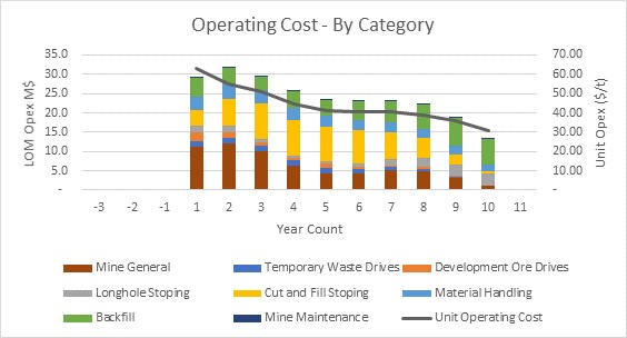
Source: Moose Mountain, 2020
Figure 21-1 Total Mine Operating Cost
21.4.2.1 Operating Cost for Terronera Deposit
Figure 21-2 shows the year-on-year mine operating cost for the Terronera deposit for various categories.
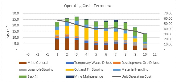
Source: Moose Mountain, 2020
Figure 21-2 Operating Cost for Terronera Deposit
21.4.2.2 Operating Cost for La Luz Deposit
Figure 21-3 shows the year-on-year mine operating cost for the La Luz deposit for various categories.
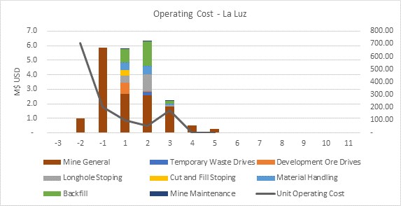
Source: Moose Mountain, 2020
Figure 21-3 Operating Cost for La Luz Deposit
21.4.3 Process Plant Operating Costs
The process plant operating costs include costs for power, reagents and consumables, labours for plant operation and maintenance, maintenance consumables, vehicles and G&A. The total process plant operating costs are summarized in Table 21-20.
Table 21-20 Process Operating Cost Summary (US$)
Description | Average Annual Costs (US$ 000’s) | Unit Cost (US$/t) |
Power | 3,861 | 6.94 |
Reagents & Consumables | 2,402 | 4.32 |
Labour (Plant & Maintenance) | 2,688 | 4.83 |
Maintenance Consumables | 591 | 1.06 |
Vehicles | 347 | 0.62 |
G&A | 3,426 | 6.16 |
Total | 13,315 | 23.94 |
21.4.3.1 Power Costs
Annual power costs were calculated using a unit cost of $0.14/kWh for the process plant and an estimated annual power consumption when operating at 1,600 tpd. Annual power costs for camp utilities were calculated using a unit cost of $0.10/kWh. Electricity is planned to be generated to the process plant using natural gas and solar, while camp utilities are planned to use grid power.
The process plant power consumption was derived from the average power utilization of each motor on the electrical load list for the process plant. Annual power consumption was then estimated to be 30 GWh.
Table 21-21 shows the average annual power costs for the Project. Annual operating costs for power consumption are estimated at $4.03 M.
Table 21-21 1,600 tpd Power Demand (kW)
Equipment | Annual Power Costs ($M) |
Mine | 0.17 |
Process Plant, Filter Plants & Other Facilities | 3.86 |
Total | 4.03 |
Note: Figures may not sum due to rounding.
21.4.3.2 Reagents and Consumables Costs
Individual reagent consumption rates were estimated based on the metallurgical testwork results, Ausenco’s in-house database and experience, industry practice, client-provided data and peer-reviewed literature.
Other consumables for crushing, screening, grinding and filtration (e.g. crushers liners, mantles, ball mill ball media, filter cloths, etc) were estimated using metallurgical testing results (abrasion), Ausenco’s in-house calculation methods, and benchmarking against other pre-feasibility studies and operations within Canada, North America, and South America. Table 21-22 shows the breakdown of each reagent and consumable costs per annum and cost per tonne milled.
Table 21-22 Reagents and Consumables Operating Costs (US$)
Reagents & Consumables | Average Annual Cost (US$ 000’s) |
Crushing/Screening | |
Primary Jaw Crusher | 58 |
Secondary Cone Crusher | 84 |
Tertiary Cone Crusher | 75 |
Vibrating Screen | 259 |
Ball Mill | 1,047 |
Reagents | |
PAX | 130 |
MIBC | 94 |
Flocculant CIBA MF 155 | 70 |
Others | |
Concentrate Filter FFP 2512 40/50 M50 | 285 |
Tailings Filter CX12-204 | 418 |
Total | 2,796 |
Note: Figures may not sum due to rounding
Reagents and consumables represent approximately 18% of the total LOM process operating cost.
21.4.3.3 Labour Costs
Staffing and salaries were provided by Endeavour Silver as well as estimated by benchmarking against similar projects. The labour costs incorporate requirements for the process plant such as management, metallurgy, operations, maintenance, assay laboratory, and contractor allowance. The total operational labour averages 115 employees. Rates provided by Endeavour Silver include the specific benefits and allocated bonuses as well as social burden costs. Thus, these rates were considered as overall rates.
Table 21-23 summarizes the labour costs when the plant is operating at 1,600 tpd.
Table 21-23 Labour Operating Costs (US$ 000’s)
| Average Annual Cost (US$ 000’s) |
Process Plant Administrative | 447 |
Process Plant General | 630 |
Maintenance | 1,431 |
Laboratory | 314 |
Total | 2,823 |
Note: Figures may not sum due to rounding
21.4.3.4 Maintenance Consumables Costs
Annual maintenance consumables costs were calculated based on total installed mechanical capital cost by area using a weighted average factor from 3% to 5%. The factor was applied to mechanical equipment, platework, and piping. The total maintenance consumables operating cost is $1.06/t milled, or approximately 4.9% of the mechanical capital cost. This is then estimated to be approximately 4% of the total process operating cost.
21.4.3.5 Vehicles Costs
Vehicles were estimated by benchmarking against similar projects. Vehicles costs were based on a scheduled number of light vehicles (administration, water supply needs, site roads, safety and emergency) and process plant mobile equipment, including fuel, maintenance, spares and tired, and annual registration and insurance fees.
Vehicle costs are estimated at $0.62/t milled and represent approximately 3% of the total LOM process operating cost.
21.4.3.6 G&A Operating Costs
General and administrative costs were developed with input from Endeavour Silver, as well as using Ausenco’s in-house data on existing Canadian operations.
The G&A operating costs include warehousing, purchasing, environmental, human resources, laboratory resources, camp, security, information technology, accounting, administration, community relations, legal, and safety.
The G&A services and staffing were developed with input from Endeavour Silver. General and administrative manpower rates for the Terronera Project were provided by Endeavour Silver, while other G&A rates were estimated by benchmarking against similar projects to develop the total G&A cost.
The total G&A unit cost is estimated at $6.16/t milled and the annual G&A cost over the LOM is at $3.42 M/a.
21.4.4 Dry-Stack Tailings Storage Facility Operating Costs
Operating costs for the TSF include personnel for operating, maintenance, environmental monitoring, dam-safety-related surveillance, and provision of a light vehicle. These costs are included with the process operating costs. Supporting engineering studies, investigations, design, construction supervision, dam-safety-related inspections, and general consulting costs are included with the engineering costs covered by Ausenco. The total operating cost for the TSF is summarized in Table 21-24.
Table 21-24 Dry Tailings Storage Facility Operating Costs (US$)
Description | LOM Cost (US$ 000’s) |
Filtered Tailings Hauling, Placement and Compaction | 5,567 |
Operation Road on TSF Face Slope | 350 |
Surface Preparation | 259 |
Non-Contact Water Management | 924 |
Contact Water Management | 196 |
Contact Water Pond System | 409 |
Erosion Control | 2789 |
TSF Instrumentation | 280 |
Total TSF Operating Cost | 8,263 |
Unit Operating Cost ($/t) | 1.49 |
Note: Figures may not sum due to rounding
22.1 Cautionary Statement
The results of the economic analyses discussed in this section represent forward-looking information as defined under Canadian securities law. The results depend on inputs that are subject to several known and unknown risks, uncertainties, and other factors that may cause actual results to differ materially from those presented herein. Information that is forward-looking includes the following:
• Proven and Probable Mineral Reserves that have been modified from Measured and Indicated Mineral Resource estimates
• Assumed commodity prices and exchange rates
• Proposed mine production plan
• Projected mining and process recovery rates
• Assumptions about mining dilution and the ability to mine in areas previously exploited using underground mining methods as envisaged
• Sustaining costs and proposed operating costs
• Interpretations and assumptions regarding agreement terms
• Assumptions as to closure costs and closure requirements
• Assumptions as to ability to permit the project
• Assumptions about environmental, permitting, and social risks.
Additional risks to the forward-looking information include:
• Changes to costs of production from what is assumed
• Unrecognised environmental risks
• Unanticipated reclamation expenses
• Unexpected variations in quantity of mineralised material, grade or recovery rates
• Geotechnical or hydrogeological considerations during mining being different from what was assumed
• Failure of mining methods to operate as anticipated
• Failure of plant, equipment, or processes to operate as anticipated
• Changes to assumptions as to the availability of electrical power, and the power rates used in the operating cost estimates and financial analysis
• Ability to maintain the social licence to operate
• Accidents, labour disputes and other risks of the mining industry
• Changes to interest rates
• Changes to tax rates.
Calendar years used in the financial analysis are provided for conceptual purposes only. Permits still must be obtained in support of operations; and approval to proceed is still required from Endeavour Silver’s Board of Directors.
22.2 Methodology Used
An economic model was developed to estimate annual pre-tax and post-tax cash flows and sensitivities of the Project based on a 5% discount rate. It must be noted that tax estimates involve complex variables that can only be accurately calculated during operations and, as such, the after-tax results are approximations. A sensitivity analysis was performed to assess the impact of variations in metal prices, initial capital cost, total operating cost, feed grade and discount rate.
The capital and operating cost estimates developed specifically for this Project are presented in Section 21 of this report in Q2 2020 US dollars. The economic analysis has been run on a constant dollar basis with no inflation.
22.3 Financial Model Parameters
A base case gold price of US$1,419/oz and silver price of US$15.97/oz are based on two-year trailing averages as of 08th July, 2020. The forecasts are meant to reflect the average metal price expectation over the life of the Project. No price inflation or escalation factors were considered. Commodity prices can be volatile, and there is the potential for deviation from the forecast.
The economic analysis was performed using the following assumptions:
• Construction starting March 1, 2022
• All construction costs capitalised in Year -2
• Commercial production starting (effectively) on September 1, 2023
• LOM of 10 years
• Cost estimates in constant Q2 2020 US dollars with no inflation or escalation
• 100% ownership with 2% royalty to IMMSA and 0.5% to Mexican government
• Capital costs funded with 100% equity (no financing costs assumed)
• All cash flows discounted to March 1, 2022
• Silver and gold are assumed to be sold in the same year they are produced
• No contractual arrangements for refining currently exist.
22.4 Taxes
The Project was evaluated on an after-tax basis to provide an approximate value of the potential economics. The tax model was compiled by Endeavour Silver with assistance from third-party taxation professionals. The calculations are based on the tax regime as of the date of the UPFS and include estimates for Endeavour Silver’s expenditures, and related impacts to various tax pool balances, between the UPFS and the assumed construction start date.
At the effective date of this report, the Project was assumed to be subject to the following tax regime:
• Corporate tax rate of 30%
• Mexico mining tax rate of 7.5%
• Beginning net operating loss of US$61.4 M was assumed for tax purposes
• Total undiscounted tax payments are estimated to be US$97.5 M over the LOM.
22.5 Working Capital
Working capital and initial fills are included as part of initial capital and assumed to be recovered in the final years of operation. The effective sum of working capital and initial fills over the life of mine is zero.
22.6 Closure Costs & Salvage Value
The projects closure cost was estimated to be US$5.0 M and an estimated salvage value of US$3.0 M was allocated in the economic analysis. Both closure costs and salvage costs are assumed to be incurred in the year after final production.
22.7 Royalty
A 2.5% royalty was assumed for the project out of which 2% royalty is the property royalty to IMMSA and 0.5% is the royalty to Mexican government, resulting in approximately US$22 M in undiscounted royalty payments over the LOM.
22.8 Economic Analysis
The economic analysis was performed assuming a 5% discount rate. The pre-tax NPV discounted at 5% is US$205 M; the internal rate of return IRR is 37.6%; and the payback period is 2.3 years. On an after-tax basis, the NPV discounted at 5% is US$137 M; the IRR is 30.0%; and the payback period is 2.7 years. A summary of project economics is shown graphically in Figure 22-1and listed in Table 22-1. Cashflow on an annualised basis is summarised in Table 22-2.
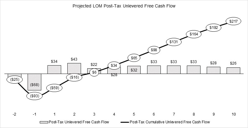
Source: Ausenco 2020.
Figure 22-1 Project Economics Graph
Table 22-1 Summary of Project Economics
General | LOM Total / Avg. |
Gold Price (US$ / oz) | 1,419 |
Silver Price (US$ / oz) | 15.97 |
Mine Life (Years) | 10 |
Total Mill Feed (kt) | 5,563 |
Production | LOM Total / Avg. |
Mill Head Grade Au (g / t) | 2.29 |
Mill Recovery Au (%) | 82.3 |
Total Recovered Ounces Au (koz) | 336.9 |
Average Annual Production Au (koz) | 33.7 |
Mill Head Grade Ag (g / t) | 201.1 |
Mill Recovery Ag (%) | 84.9 |
Total Recovered Ounces Ag (koz) | 30,602 |
Average Annual Production Ag (koz) | 3,060 |
Operating Cost | LOM Total / Avg. |
Mining (US$ / t Milled) | 35.6 |
Mining Lease (US$ / t Milled) | 8.2 |
Processing (US$ / t Milled) | 17.8 |
G&A (US$ / t Milled) | 6.2 |
Capital Cost | LOM Total / Avg. |
Initial Capex (US$M) | 99.1 |
Sustaining Capex (US$M) | 60.4 |
Pre-Tax Financial | LOM Total / Avg. |
NPV (5%) (US$M) | 205 |
IRR (%) | 37.6 |
Payback (Years) | 2.3 |
Post-Tax Financial | LOM Total / Avg. |
NPV (5%) (US$M) | 137 |
IRR (%) | 30.0 |
Payback (Years) | 2.7 |
Cash Cost (Net by-product per silver oz) | 0.004 |
All-in Sustaining Cost per Ag ounce | 8.96 |
Table 22-2 Project Cash Flow on an Annualised Basis
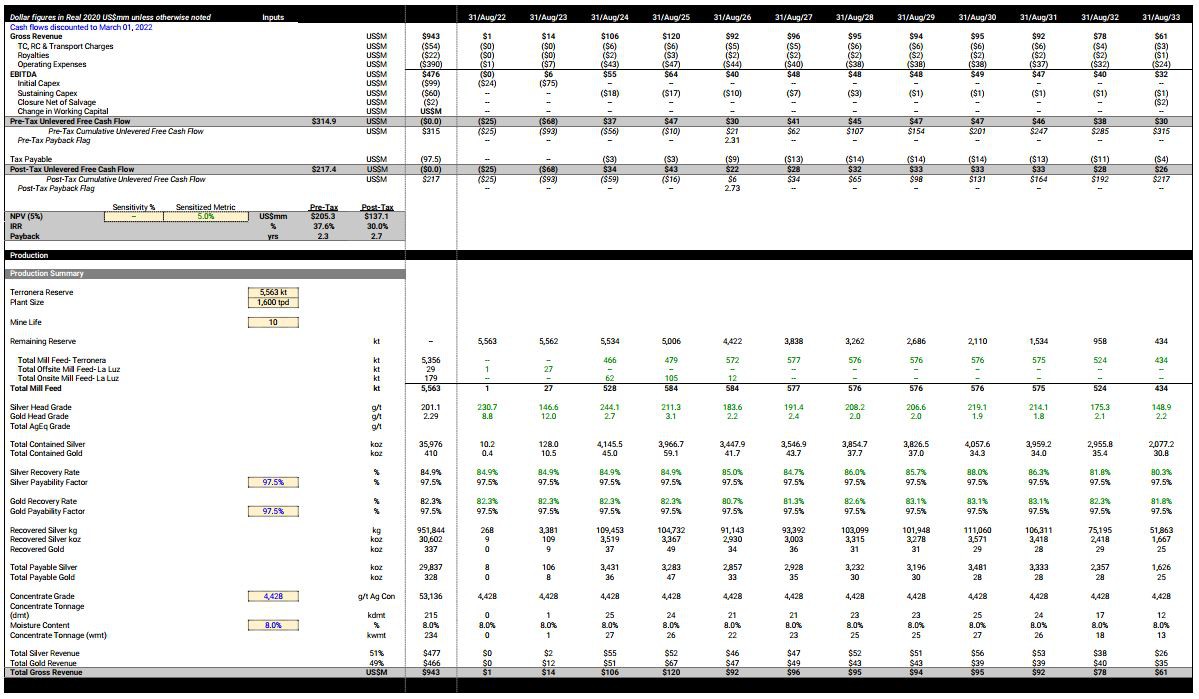
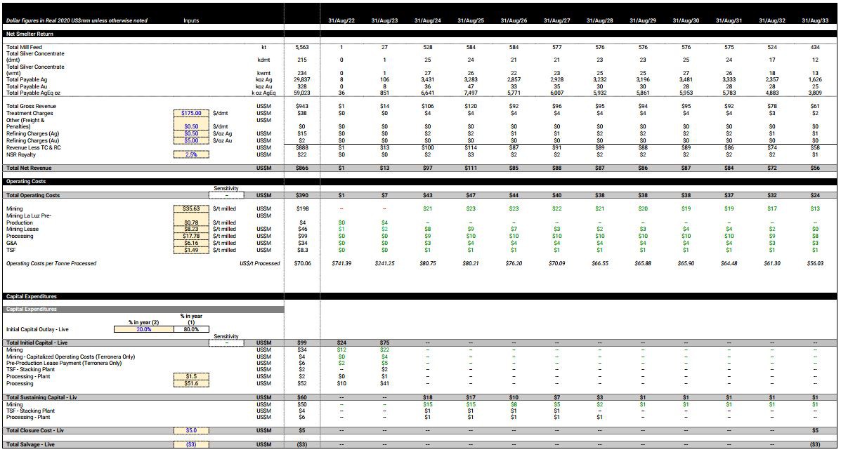
22.9 Sensitivity Analysis
A sensitivity analysis was conducted on the base case pre-tax and post-tax NPV and IRR of the project, using the following variables: metal prices, initial capital cost, total operating cost, head grade and discount rate. Table 22-3 shows the project’s pre-tax sensitivity, and Table 22-4 shows the project’s post-tax sensitivity results. The analysis revealed that the project is most sensitive to revenue attributes such as gold and silver price, followed by operating cost and discount rate.
Table 22‑3 Sensitivity to Metal Prices
Gold Price | Silver Price | After Tax NPV | After Tax IRR |
1,200 | 12.00 | 49.8 | 14.2% |
1,400 | 14.00 | 107.8 | 24.2% |
Base Case | Base Case | 137.1 | 30.0% |
1,600 | 16.00 | 164.5 | 34.9% |
1,800 | 18.00 | 220.9 | 44.4% |
2,000 | 20.00 | 277.3 | 53.9% |
Table 22‑4 Sensitivity to CAPEX
Movement | OPEX NPV | OPEX IRR | CAPEX NPV | CAPEX IRR |
-20% | 173.2 | 36.2% | 150.4 | 38.1% |
-10% | 155.2 | 33.1% | 143.8 | 33.6% |
Base Case | 137.1 | 30.0% | 137.1 | 30.0% |
10% | 118.9 | 26.7% | 130.4 | 26.9% |
20% | 100.7 | 23.4% | 123.7 | 24.3% |
Table 22-5 Pre-Tax Sensitivity
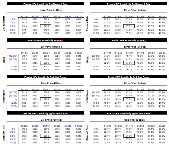
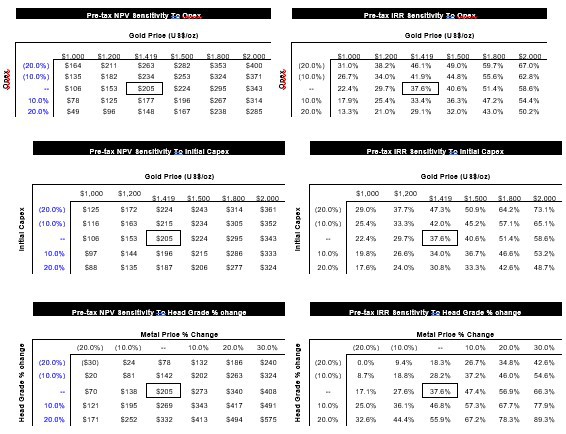
Table 22-6 Post-Tax Sensitivity
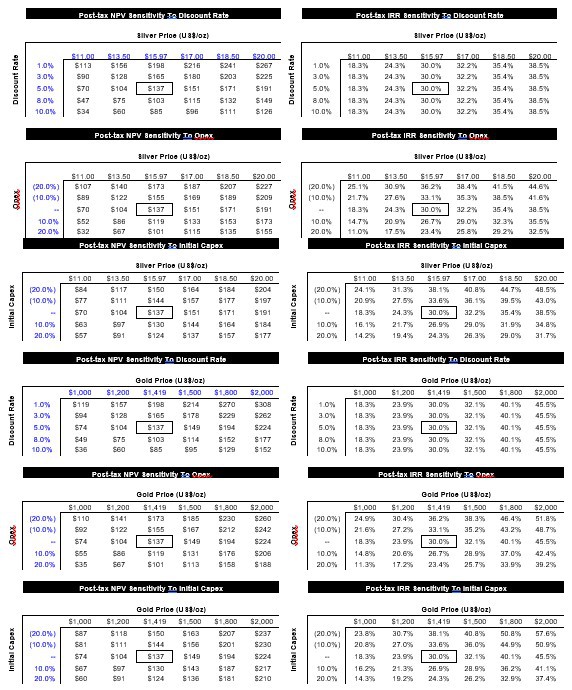
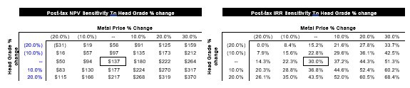
This section is not relevant to this Report.
24 Other Relevant Data and Information
This section is not relevant to this Report.
25 Interpretation and Conclusions
25.1 Exploration
Since 2010 Endeavour Silver has conducted exploration activities on the Terronera Project, including data compilation, field mapping, surface sampling, trenching, soil geochemistry surveys. Work was done over the various structures on the property, including the Terronera Vein, the Real Alto, La Zavala, Quiteria West, La Ermita and La Luz areas.
25.2 Drilling
Endeavour Silver began drilling at the Real Alto and Quiteria West Targets in 2011. Drilling over the Terronera Vein was conducted from early 2012 to the end of 2016. Nine drilling objectives were tested in 2016, including La Luz. Between 2011 and 2016, Endeavour Silver had drilled 70,885 m in 248 diamond drill holes over the entire Terronera Project. During 2017, a total of 12,252 m drilled in 47 drill holes, mainly conducted at La Luz. During 2018, a total of 18,774 m drilled in 39 surface diamond drillholes, were advanced on the Terronera Vein including 3,007 samples collected and submitted for analysis.
In 2018, Endeavour Silver engaged Knight Piésold Ltd. to provide geomechanical and hydrogeological support for the proposed underground mine over La Luz Vein of the Terronera Project.
25.3 Sample Preparation, Analyses & Security
Since September, 2014 sampling has coincided with core recovery. Drilling is subject to daily scrutiny and coordination by Endeavour Silver’s geologists. A QA/QC program of blanks, duplicates, reference standards and check assays has been instituted by Endeavour Silver to monitor the integrity of assay results. Drilling on the Terronera Project included a QA/QC program.
A total of 3,007 samples, including control samples, were submitted during Endeavour Silver’s surface drilling program at Terronera from March 2018 through August 2018. A total of 148 pulps were also submitted for check assaying.
25.4 Data Verification
P&E conducted verification of the drill hole assay database by comparison of the database entries with the assay certificates, which were sent to P&E in digital format directly from ALS, no errors were noted.
P&E considers there to be good correlation between the majority of P&E’s independent verification samples analyzed by ALS and the original analyses in the Terronera and La Luz databases.
Based upon the evaluation of the QA/QC program undertaken by Endeavour Silver and P&E’s due diligence sampling, it is P&E’s opinion that the results are acceptable for use in the current Mineral Resource estimate.
25.5 Resources, Reserves and Mining
25.5.1 Mineral Resource Estimate
The Mineral Resource estimate for Terronera was undertaken by Yungang Wu, P.Geo., and Eugene Puritch, P.Eng., FEC, CET of P&E Mining Consultants Inc., Brampton, Ontario, both independent Qualified Persons in terms of NI 43-101, from information and data supplied by Endeavor Silver. The effective date of this Resource Estimate is May 10, 2020.
All drilling and assay data were provided in the form of Excel data files by Endeavour Silver. The Gems database for this Mineral Resource estimate, constructed by P&E, consisted of 195 drill holes totalling 65,083 m and 36 channel samples totalling 77.25 m, of which 39 drill holes totalling 18,774 m were drilled in 2018.
A total of six (6) mineralization vein wireframes were generated during the course of this Mineral Resource estimate. A cut-off grade of 150 g/t silver equivalent (AgEq) was applied to the wireframes. The AgEq was calculated with a formula of AgEq=Ag + (Au x 75). The wireframes were created from successive polylines on N50E orientated vertical cross-sections with a 25 m spacing. In some cases, mineralization below the above mentioned 150 g/t AgEq cut-off was included for the purpose of maintaining zonal continuity.
Grade capping was investigated on the 1.0 m composite values in the database within the constraining domains to ensure that the possible influence of erratic high values did not bias the database. The capped composites were utilized to develop variograms and for block model grade interpolation.
The Terronera Mineral Resource block model was constructed using Geovia GEMSTM V6.8 modelling software. The block model consists of separate models for estimated grade, rock type, volume percent, bulk density and classification attributes.
P&E considers that the silver and gold mineralization of Terronera Deposit is potentially amenable to underground extraction. The resulting Mineral Resource estimate is tabulated in the Table 25-1.
Table 25-1 Terronera Mineral Resource Estimate at a cut-off grade of 150 g/t Ag Eq. (1-6)
Classification | Tonnes (kt) | Ag (g/t) | Contained Ag (koz) | Au (g/t) | Contained Au (koz) | AgEq (g/t) | Contained AgEq (koz) |
Indicated | 5,275 | 227.2 | 38,537 | 2.35 | 398 | 403.4 | 68,416 |
Inferred | 1,022 | 212.2 | 6,970 | 1.70 | 56 | 339.8 | 11,161 |
1. Mineral Resources which are not Mineral Reserves do not have demonstrated economic viability. The estimate of Mineral Resources may be materially affected by environmental, permitting, legal, title, taxation, socio-political, marketing, or other relevant issues.
2. The Inferred Mineral Resource in this estimate has a lower level of confidence than that applied to an Indicated Mineral Resource and must not be converted to a Mineral Reserve. It is reasonably expected that the majority of the Inferred Mineral Resource could be upgraded to an Indicated Mineral Resource with continued exploration.
3. The Mineral Resources in this Updated Technical Report were estimated using the CIM Definition Standards for Mineral Resources and Mineral Reserves.
4. AgEq g/t = Ag g/t + (Au g/t x 75)
5. Historical mined areas were depleted from the Terronera Vein wireframe and Mineral Resource model.
6. Mineral Resources are inclusive of Mineral Reserves.
The Mineral Resource estimate for La Luz was undertaken by Yungang Wu, P.Geo., and Eugene Puritch, P.Eng., FEC, CET of P&E Mining Consultants Inc., Brampton, Ontario, both independent Qualified Persons in terms of NI 43-101, from information and data supplied by Endeavor Silver. The effective date of this Resource Estimate is August 1, 2018.
All drilling and assay data were provided in the form of Excel data files by Endeavour Silver. The Gems database for this Mineral Resource estimate, constructed by P&E, consisted of 41 diamond drill holes totalling 9,795.65 meters completed in 2016 and 2017.
Two (2) mineralized veins were generated during the course of this Mineral Resource estimate. A cut-off grade of 150 g/t silver equivalence (AgEq) was applied to the wireframes. The AgEq was calculated with a formula of AgEq = Ag + (Au x 75). The wireframes were created from successive polylines on west facing vertical cross-sections with 50m spacing. In some cases mineralization below the above mentioned 150 g/t AgEq cut-offs was included for the purpose of maintaining zonal continuity.
Grade capping was investigated on the 1.0 m composite values in the database within the constraining domains to ensure that the possible influence of erratic high values did not bias the database. The capped composites were utilized to develop variograms and for block model grade interpolation.
The La Luz Mineral Resource block model was constructed using Geovia GEMSTM V6.8 modelling software. The block model consists of separate models for estimated grade, rock type, volume percent, bulk density and classification attributes.
P&E considers that the silver and gold mineralization of La Luz Deposit is potentially amenable to underground extraction. The resulting Mineral Resource estimate is tabulated in the Table 25-2.
Table 25-2 La Luz Mineral Resource Estimate at a cut-off grade of 150 g/t Ag Eq. (1-4)
Class-ification | Tonnage (kt) | Ag (g/t) | Contained Ag (koz) | Au (g/t) | Contained Au (koz) | AgEq (g/t) | Contained AgEq (koz) |
Indicated | 126 | 192 | 779 | 13.60 | 55 | 1,212 | 4,904 |
Inferred | 58 | 145 | 269 | 12.15 | 23 | 1,060 | 1,994 |
1. Mineral Resources which are not Mineral Reserves do not have demonstrated economic viability. The estimate of Mineral Resources may be materially affected by environmental, permitting, legal, title, taxation, socio-political, marketing, or other relevant issues.
2. The Inferred Mineral Resource in this estimate has a lower level of confidence than that applied to an Indicated Mineral Resource and must not be converted to a Mineral Reserve. It is reasonably expected that the majority of the Inferred Mineral Resource could be upgraded to an Indicated Mineral Resource with continued exploration.
3. The Mineral Resources in this report were estimated using the Canadian Institute of Mining, Metallurgy and Petroleum (CIM), CIM Standards on Mineral Resources and Reserves, Definitions and Guidelines prepared by the CIM Standing Committee on Reserve Definitions and adopted by the CIM Council.
4. AgEq g/t = Ag g/t + (Au g/t x 75).
25.5.2 Mineral Reserve Estimate
Proven and Probable mineral reserves have been modified from Measured and Indicated mineral resources at Terronera. Inferred Mineral Resources were set to waste. The Mineral Reserves are supported by the UPFS mine plan.
Factors that may affect the Mineral Reserve estimates include mining method, mine design, metal prices, changes in interpretations of mineralisation geometry and continuity of mineralisation zones, geotechnical and hydrogeological assumptions, ability of the mining operation to meet the annual production rate, operating cost assumptions, process plant and mining recoveries, the ability to meet and maintain permitting and environmental licence conditions, and the ability to maintain the social licence to operate.
25.5.3 Mine Plan
Reasonable mine plans, mine production schedules, and mine capital and operating costs have been developed for Mineral Reserves at Terronera and La Luz.
The mine plan supports the cash flow model and financials developed for the UPFS.
25.6 Metallurgical Testwork and Processing
Application of the 2019 PFS process plant design is technically feasible for production of silver and gold concentrate at a design capacity of 1,600 tpd. The process steps are conventional and mature. In an effort to better define the plant design parameters, limited metallurgical testwork was conducted to confirm the primary grind size and flotation circuit design. The testwork supported 70 microns primary grind size and elimination of the re-grind mill in the cleaner flotation circuit. Silver minerals were relatively coarse and all testworks indicated the target 4,500 g/t grade was achievable without the aid of re-grind mill in the cleaner flotation circuit.
Both historical and 2019 PFS metallurgical testing were limited and no variability samples were tested with respect to the mine life lithological domains or deleterious minerals. Further metallurgical testwork encompassing the variability aspect of samples is recommended in the next phase of study.
25.7 Site Infrastructure
The infrastructure will consist of two underground mines, a processing plant, TSF, mine services, roads, camp, and power plant.
The Project site is accessible through existing public roads. Existing roads within the site connect the public roads to the proposed process plant location. Internal roads exist that connect the process plant to the two deposits and the TSF which need to be upgraded. New roads will be built from the first Terronera portal to the other two portals.
The site is located close to the town of San Sebastian. The majority of the workforce will be hired locally. Accommodation will be provided to the employees and contractors through an accommodations camp. The project will include a 400-person camp that will be located in the town of Santiago de los Pinos. Any excess accommodations requirements during construction or operation will be met through accommodations in the nearby towns.
Power to the site will be provided through an onsite natural gas-solar power generation plant. Only the camp will be powered through national grid due to its close proximity to the grid line.
Previous studies have identified several sources of water at the site. It is assumed that the underground water would meet the plant requirement. The plant would need only 15.6 m3/hr of fresh water and the balance water will be recirculated. The site experiences 300-400 mm of rainfall during the rainy season. Excess contact water during those seasons will be collected in settling ponds before discharging out.
25.8 Environmental Studies, Permitting and Social Impact
A modified environmental impact statement (MIA) application will be submitted as per the revised production rate of 1600 tpd. This modification will require public notification, participation and continued engagement with the community to follow the status of the project and the proposed milestones for development and execution of the project.
Additional change of land use (ETJ) permits are in progress for the proposed La Luz and Terronera temporary waste rock facilities. Also, permits to occupy the federal riverbed for both of these facilities will be required and are in the process of being prepared for submission to the local regulators.
25.9 Capital & Operating Costs
AACE Class 4 costs have been developed for this pre-feasibility study, with an accuracy of ±25%, based on vendor quotations and consultants’ experience for the Project as described in this Report. Additional engineering is required, but project development is sufficient at this point for a pre-feasibility study.
The overall capital cost estimate is $99.1M.
Unit operating costs are estimated at $70.1/t.
The sustaining costs estimate is $60.4M.
25.10 Economic Analysis
The Project shows positive economics as per the design and assumptions used in this study. The economic analysis showed that the pre-tax NPV discounted at 5% is $205 M; the IRR is 37.6%; and payback period is 2.3 years. On an after-tax basis, the NPV discounted at 5% is $137 M; the IRR is 30.0%; and the payback period is 2.7 years.
The project is most sensitive to revenue attributes such as gold price and head grade, followed by operating cost and capital cost.
The economic model does not consider pre-construction costs that are required to advance the project from the PFS stage to construction such as feasibility study costs, additional drilling and testwork.
25.11 Opportunities
The 2020 UPFS identified several opportunities to further improve the project economics by reducing costs and increasing the revenue. The following opportunities are identified:
• Further replacing the cut and fill mining method by low cost mining method to reduce the cut-off grade
• Higher recoveries for both Terronera and La Luz deposits by optimizing the metallurgical testwork
• Due to the lower estimated power requirement for the project, there is an opportunity to revise the power cost which includes a fixed component related to the capital and an variable component
• Higher feed grade due to the inclusion of lost metal in dilution resulting in high revenue
• Implementation of emerging technologies such as ore sorting and Woodgrove’s direct flotation reactor (DFR) to decrease unit operating costs.
25.12 Risk
The project is subject to technical, legal, environmental, and political risks.
The capital and operating costs are not subjected to any significant, unidentified or uncertain risks that could affect the estimate outside the accuracy range. Some of the low risk factors identified are listed below:
• The basis of inspection of the used El Cubo equipment was visual only.
• Metallurgical performance risk due to small sample size resulting in lack of representativeness, limited variability testing and limited testing of La Luz ore.
• Use of pressure filters instead of disk filters in the tailings filtration plant resulting in higher cost.
• Poor ground conditions resulting in additional capital costs.
• The operating cost is subject to increased G&A cost, as the typical cost at Endeavour Silver’s other operations have been higher than the industry average for similar project in Mexico.
• Reliance on the marketability of the concentrate based on current contracts.
• Lack of definition of the deleterious elements may add additional marketing costs.
• Transportation cost for transport of ore from La Luz to Bolanitas tolling mill and concentrate to port is as assumption which may change.
• The project is also subject to risks from construction delays, interruptions or delays for market access, fluctuations in commodity pricing, variation in supply costs, permitting delays and, delays or restrictions due to ongoing pandemic or unforeseen events in the future causing shutdowns.
The Qualified Persons consider these risks to be manageable and should not have an adverse effect on the continued development of the Terronera Project.
The financial analysis of this UPFS demonstrates that the Terronera Project has robust economics to develop the project through feasibility and detailed engineering.
26.1 Drilling
Endeavour Silver should continue with the company’s infill and exploratory drill program strategies. Infill drilling should be orientated to investigate the continuity of silver-gold mineralisation both along strike and at depth to improve and further validate the confidence in the geological models being used for the deposits. Infill drilling should be considered to increase the volume and tonnage of the current deposits and advance the deposit knowledge toward higher levels of mineral resource classification.
Exploratory drilling should be used in collaboration with geophysical interpretations to test for mineralisation and potential expansion of both the Terronera and La Luz deposits.
26.2 Mineral Resource Estimations
Based on the work completed for the Mineral Resource estimate, it is recommended that future Mineral Resource estimations further refine the constraining mineralised domains. Endeavour Silver should consider redefining the cut-off grade due to the low-cost mining method adopted and increase in metal prices.
26.3 Mineral Reserve and Mining Methods
The following recommendations are made for future mining studies:
• Explore opportunities to increase project value via reductions in planned mining loss and dilution and various ore control strategies:
o Explore impacts to the mine plan of re-blocking resource model
o Explore converting to a block percentage model and applying a manual dilution skin to mineralisation zones; further definition of mineralisation boundaries would be required to execute this strategy
o Explore the impacts of applying ore sorting technologies between the mine and mill
o Further work on comparing mining methods to evaluate costs versus payable metal recovered
• Conduct additional hydrogeological fieldwork, including Packer testing, piezometer installation, and development of a 3D hydrogeological model for each deposit.
• Execution of the following geotechnical work programs:
o Targeted geotechnical drilling at Terronera and La Luz deposits to increase data confidence for feasibility level engineering;
o Ground-truthing of possible major structures;
o Additional geomechanical testing leading to an updated rock mass model;
o Update the geotechnical models and perform advanced numerical modelling;
o Geotechnical analysis of the foundations identified for the Terronera and La Luz mines should be carried out to ensure suitability of site selections presented in this study.
• Drill and blast testing to be carried out by drilling vendors and local explosives suppliers by analysing local rock types and conditions to assess the achievable drill penetration rates, optimal explosives mix and target powder factor for use in this operation.
• Blasting for improved mine to mill performance can be optimised in future studies. Increased fragmentation can increase the grind capacity in the mill.
• Further engagement with potential mining contractors, obtaining updated quotations for services.
• Updates to detailed designs of the mines, infrastructure and external haul roads based on information gathered in the above studies.
• Explore opportunities to increase project value via alternative deposit development strategies.
26.4 Metallurgical Testwork
A full feasibility study level metallurgical testwork program incorporating testwork on major lithological characterisation samples, variability samples, and production composite samples from both Terronera and La Luz deposits is recommended to provide further definition across the resource. Drill cores are available on site for the testwork and the sample selection program is currently under progress. Key recommendations include:
• Ore competency – Given the limited dataset for ore competency, additional JK Tech SMC tests (Axb) are recommended to be conducted over a range of rock types and spatial zones to define distribution and variability of ore competency; PQ core is recommended;
• Ore hardness – RWi, BWi index tests should be conducted to define ore hardness distribution and variability;
• Abrasion Index – Tests should be conducted to redefine the abrasion index;
• Further testwork to optimize the grinding circuit;
• Grade-recovery relationship – Flotation testing of additional samples at various grind sizes should be conducted to determine grade-recovery relationship;
• Preconcentration – Evaluate preconcentration opportunities such as ore sorting to reduce operating costs and decrease cut-off grades;
• Solid-liquid separation – Finalise the tailings deposition route based on optimised flowsheet conditions.
26.5 Recovery Methods
The following activities are recommended to support refinements in processing plant design:
• Geotechnical site investigations should be carried out at the preferred process plant site locations to characterise the foundation conditions associated with the proposed buildings;
• Material flowability testwork should be completed to further develop the crushing and stockpile circuit design.
26.6 Site Infrastructure
The following activities are recommended to support the design of the site infrastructure beyond the UPFS and into the feasibility study:
• Geotechnical site investigations should be carried out at the preferred surface infrastructure site locations to characterise the foundation conditions associated with the proposed buildings.
• The access road to site should be further analysed, reviewed and engineered, culminating in a detailed work package to be tendered to local contractors.
• Alternate sources of power supply should be considered to decrease the footprint and earthworks required.
• Conduct studies to evaluate alternate source of water and, requirements for water treatment.
26.7 Water Management
The following activities are recommended to support the design of the water management systems:
• Maintain adequate component waterbody setbacks to account for regulatory buffers and water management infrastructure;
• Identify opportunities to enhance sedimentation pond volumes at select locations;
• Continue geochemical testing and assessment of acid rock drainage/metals leaching to further refine parameters of potential concern;
• Additional hydrogeological data should be collected to accurately estimate the underground pumping requirements;
• Conduct a site wide water balance and develop water disposal strategy meeting the environmental regulations.
26.8 Dry-Stack Tailings Management Facility
Advance the DTSF area design, associated hauling accessways, and tailings delivery infrastructure to construction design level in conjunction with feasibility level analysis.
The following activities are recommended to support the DTMF:
• Condemnation drilling for the selected site to verify the absence of ore mineralisation
- Optimize TMF area design to minimize waste rock use and maximize its availability for underground mine backfill
- Conduct a materials handling conceptual tradeoff study between conveying and trucking options, and advance to feasibility level design the selected tailings transport option.
• Consider additional land acquisition to optimize the TMF geometric design and allow for potential storage expansion
26.9 Environmental, Permitting & Community Relations
A revised EIA application should be submitted to SEMARNAT to reflect the revised production rate of 1,600 tpd.
26.10 Costs
Estimated costs for completing work recommended in this section is summarized in Table 26-1 below.
Table 26-1 Estimated Costs for Completing Work
Program Component | Cost Estimate ($M) |
Exploratory Drilling | 0.25 |
Mining – Mineral Resource and Reserve Estimate Updates | 0.5 |
Geomechanical Studies | 0.25 |
Site Geotechnical Studies | 0.20 |
Metallurgical Testing | 0.5 |
Hydrogeological Study | 0.15 |
TSF – Advance the design to construction level | 0.15 |
Environmental baseline studies and Social programs | 1.0 |
Optimization Studies | 0.3 |
Engineering Studies | 1.5 |
Total Cost | 4.80 |
AVALÚO, COMPAÑÍA MINERA DEL CUBO, S. A. de C. V.Mineral Del Cubo, Guanajuato, Gto. México, September 18, 2019
Barton, N., & Grimstad, E., (1993). The Q-system following twenty years of application in NMT support selection. 43rd Geomechanics Colloquy. Felsbau, 6/94. pp. 428-436.
Bases Licitación No. Rpg-001py-2019 Sobre El Proyecto:Desmontaje -Traslado -Montaje Y Obra Civiltaller Mecanico Santa Cecilia Cubo Gto.-Gcvi Dgo
Bieniawski Z.T., Engineering Rock Mass Classifications, John Wiley & Sons, New York, 1989.
Clark, L., 1998. Minimizing Dilution in Open Stope Mining with a Focus on Stope Design and Narrow Vein Longhole Blasting. M.Sc. thesis, Department of Mining and Mineral Process Engineering, The University of British Columbia, 316 p.
El Cubo Flowsheet, Approved for Construction, August 02, 2013
Feasibility Study Report for SilverCrest’s Las Chispas Property, Sonora, Mexico, 2020
Grupo Gixtoh, Ingeniería & Medio Ambiente S.A De C.V., Determinación De Potencial Hídrico Y Análisis De Riesgo De Afectación A Manantiales Por Actividades Mineras En La Explotación De La Mina La Terronera, San Sebastián Del Oeste, Jalisco, México, April 2020.
Heidbach, O., Tingay, M., Barth, A., Reinecker, J., Kurfeß, D., and Müller, B., The World Stress Map database release 2016 doi:10.1594/GFZ.WSM.Rel2008, 2008.
Knight Piésold Ltd. (2019), Terronera Project, Geomechanical Design Input for Pre-Feasibility Study, final report prepared for Endeavour Silver Corp. dated March 22, 2019.
Knight Piésold Ltd. (2019), Terronera Project, La Luz Deposit Underground Pre-Feasibility Study Geomechanical Design Input, draft report prepared for Endeavour Silver Corp. dated October 25, 2019.
Lewis, W.J., Murahwi, C.Z., (2012), NI 43-101 Technical Report, Audit of the Mineral Resource Estimate for the San Sebastian
Munroe, M.J., (2014), NI 43-101 Technical Report on the Resource Estimates for the San Sebastian Project, Jalisco State, Mexico, by Michael J. Munroe for Endeavour Silver Corp., March 27, 2014, 140 p
P&E Mining Consultants Inc (2019), NI 43-101 and NI 43-101F1 Technical Report, Updated Technical Report for the Terronera Project, Jalisco State, Mexico, April 30, 2019.
Panteleyev, A.(1996): Epithermal Au-Ag-Cu: High Sulphidation, in Selected British Columbia Mineral Deposit Profiles, Volume 2 – Metallic Deposits, Lefebure, D.V. and Hõy, T, Editors, British Columbia Ministry of Employment and Investment, Open File 1996-13, pages 37-39.
Potvin, Y. and Hadjigeorgiou, J., (2001) The Stability Graph for Open-Stope Design, Underground Mining Methods: Engineering Fundamentals and International Case Studies, Ed. William Hustrulid, SME, pp 513 to 520, 2001.
Prefeasibility Study documents, ENDTER02E_TEM_032_kb from JDS, March 2020
Project, Jalisco State, Mexico, by Micon International Limited for Endeavour Silver Corp., March 30, 2012, 131 p.
Trueman & Mawdesley (2003), Predicting Cave Initiation and Propagation, CIM Bulletin 96 (1071), May 2003.
Wood, 2018; Reporte de Diseño del Depósito de Jales y de Tepetate, Proyecto Terronera, San Sebastián del Oeste, Jalisco, México, Junio 8, 2018.
Wood, 2020; Updated Pre-Feasibility Study Drawings, Terronera Project, San Sebastian del Oeste, Jalisco, Mexico.

CONSENT OF QUALIFIED PERSON
I, David Burga, P.Geo., Associate Geologist of P&E Mining Consultants Inc., hereby consent to the public filing of the technical report entitled, « Endeavour Silver Corp Terronera Project NI 43-101 Technical Report” effective July 14, 2020 and dated July 31, 2020 the « Technical Report ») by Endeavour Silver Corp. (the “Company”).
I also consent to any extracts from or a summary of the Technical Report in the news release of the Company dated July 14, 2020 (the « News Release »).
I certify that I have read the News Release filed by the Company and that it fairly and accurately represents the information in the sections of the Technical Report for which I am responsible.
Dated this 31st day of July, 2020
![]()
David Burga, P.Geo.
Associate Geologist
P&E Mining Consultants Inc.

CONSENT OF QUALIFIED PERSON
I, Euqene Puritch, P.Eng., F.E.C., CET, President of P&E Mining Consultants Inc., hereby consent to the public filing of the technical report entitled, « Endeavour Silver Corp Terronera Project NI 43-101 Technical Report” effective July 14, 2020 and dated July 31, 2020 the « Technical Report ») by Endeavour Silver Corp. (the “Company”).
I also consent to any extracts from or a summary of the Technical Report in the news release of the Company dated July 14, 2020 (the « News Release »).
I certify that I have read the News Release filed by the Company and that it fairly and accurately represents the information in the sections of the Technical Report for which I am responsible.
Dated this 31st day of July, 2020

Euqene Puritch, P.Eng., F.E.C., CET
President
P&E Mining Consultants Inc.
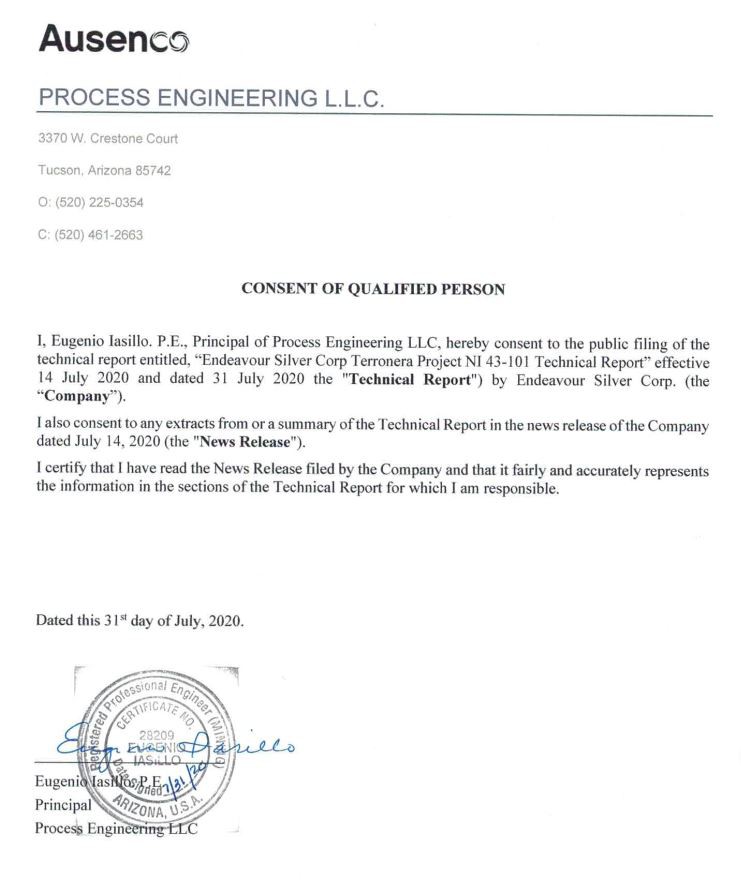
Humberto F. Preciado, P.E.
Wood Environment & Infrastructure Solutions, Inc.
2000 S Colorado Blvd
Suite 2-1000
Denver, CO 80222
USA
CONSENT OF QUALIFIED PERSON
I, Humberto Preciado, P.E, Senior Associate Geotechnical Engineer with Wood Environment & Infrastructure Solutions, Inc., hereby consent to the public filing of the technical report entitled, « Endeavour Silver Corp Terronera Project NI 43-101 Technical Report” effective date of July 14, 2020 and dated July 31, 2020 the « Technical Report« ) by Endeavour Silver Corp. (the “Company”).
I also consent to any extracts from or a summary of the Technical Report in the news release of the Company dated July 14, 2020 (the « News Release« ).
I certify that I have read the News Release filed by the Company and that it fairly and accurately represents the information in the sections of the Technical Report for which I am responsible.
Dated this 31st day of July, 2020.
_[SIGNED AND SEALED]___________
Humberto Preciado, P.E
Senior Associate Geotechnical Engineer
Wood Environment & Infrastructure Solutions, Inc.
 | JDS Energy & Mining Inc. Suite 900 – 999 West Hastings Street Vancouver, BC V6C 2W2 t 604.558.6300 jdsmining.ca |
CONSENT OF QUALIFIED PERSON
FILED BY SEDAR
I, Michael Levy, P.Eng., Geotechnical Manager of JDS Energy & Mining Inc., hereby consent to the public filing of the technical report entitled, « Endeavour Silver Corp Terronera Project NI 43- 101 Technical Report” effective July 14, 2020 and dated July 31, 2020 the « Technical Report ») by Endeavour Silver Corp. (the “Company”).
I also consent to any extracts from or a summary of the Technical Report in the news release of the Company dated July 14, 2020 (the « News Release »).
I certify that I have read the News Release filed by the Company and that it fairly and accurately represents the information in the sections of the Technical Report for which I am responsible.
Dated this 31st day of July, 2020.
(Original signed and sealed) “Michael Levy, P. Eng.”
Michael Levy, P.E.
JDS Energy & Mining, Inc.

Michael Petrina
Moose Mountain Technical Services
135 Devonshire Avenue, Iroquois Falls, Ontario, Canada
CONSENT OF QUALIFIED PERSON
I, Michael Petrina, P.Eng., Principal Mining Engineer with Moose Mountain Technical Services, hereby consent to the public filing of the technical report entitled, « Endeavour Silver Corp Terronera Project NI 43- 101 Technical Report” effective July 14, 2020 and dated July 31, 2020 the « Technical Report« ) by Endeavour Silver Corp. (the “Company”).
I also consent to any extracts from or a summary of the Technical Report in the news release of the Company dated July 14, 2020 (the « News Release« ).
I certify that I have read the News Release filed by the Company and that it fairly and accurately represents the information in the sections of the Technical Report for which I am responsible.
Dated this 31 day of July, 2020.

Michael Petrina, P.Eng.
Principal Mining Engineer
Moose Mountain Technical Services

CONSENT OF QUALIFIED PERSON
I, Robin Kalanchey, P.Eng., Director, Minerals and Metals – Western Canada of Ausenco Engineering Canada Inc., hereby consent to the public filing of the technical report entitled, « Endeavour Silver Corp Terronera Project NI 43-101 Technical Report” effective July 14, 2020 and dated July 31, 2020 the (« Technical Report« ) by Endeavour Silver Corp. the (“Company”).
I also consent to any extracts from or a summary of the Technical Report in the news release of the Company dated July 14, 2020 (the « News Release« ).
I certify that I have read the News Release filed by the Company and that it fairly and accurately represents the information in the sections of the Technical Report for which I am responsible.
Dated this 31 day of July 2020.


CONSENT OF QUALIFIED PERSON
I, Yungang Wu, P.Geo., Associate Geologist of P&E Mining Consultants Inc., hereby consent to the public filing of the technical report entitled, « Endeavour Silver Corp Terronera Project NI 43-101 Technical Report” effective July 14, 2020 and dated July 31, 2020 the « Technical Report ») by Endeavour Silver Corp. (the “Company”).
I also consent to any extracts from or a summary of the Technical Report in the news release of the Company dated July 14, 2020 (the « News Release »).
I certify that I have read the News Release filed by the Company and that it fairly and accurately represents the information in the sections of the Technical Report for which I am responsible.
Dated this 31st day of July, 2020

Yungang Wu, P.Geo.
Associate Geologist
P&E Mining Consultants Inc.